
Fan condition detecting method and apparatus therefor

A state detection device and state detection technology, which are used in measurement devices, pump devices, linear/angular velocity measurement, etc., can solve the problem of high cost of detection equipment, and achieve economical realization and good scalability.

Inactive Publication Date: 2005-01-19
HUAWEI TECH CO LTD
View PDF0 Cites 8 Cited by
  • Summary
  • Abstract
  • Description
  • Claims
  • Application Information

AI Technical Summary

Problems solved by technology

[0007] The invention provides a fan state detection method and device to solve the problem of high cost of detection equipment for fans without detection signal output in the prior art

Method used


Image

  • Fan condition detecting method and apparatus therefor
  • Fan condition detecting method and apparatus therefor
  • Fan condition detecting method and apparatus therefor

Examples


Embodiment Construction

[0035] The present invention will be further described below in conjunction with the accompanying drawings.

[0036] The present invention detects the state of the fan by extracting the fan speed pulse signal. The fan speed pulse signal is one of the inherent characteristics of the fan, that is, the rotation of the fan will inevitably generate a speed pulse signal. If there is a speed pulse signal, the fan must be turning. In other words, the presence or absence of the speed pulse signal shows whether the fan is turning or not. , the high or low frequency shows the speed of the fan speed.

[0037] For the speed pulse signal, generally 2 to 3 pulses are output per revolution. By counting the speed pulses, the speed of the fan can be calculated, and the state of the fan can also be known. When the fan stops, the speed pulse signal is normally low or high.

[0038] In addition, in the fan circuit, in order to control the speed of the fan, there is a switch tube in the fan circu...


PUM


Abstract

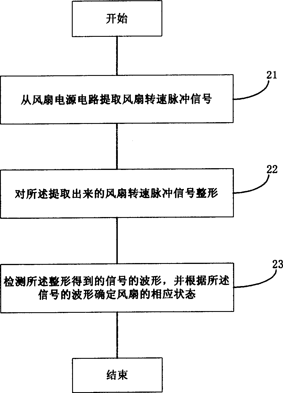
This invention discloses a detecting method for fan status and its apparatus. The steps of the said method are the following: a, to extract fan rotation impulse signals from fan power circuit; b to shape the said fan rotation impulse signals; c, to detect wave shape of the signals and to determine the relevant status according to the signals. The said apparatus comprises extracting device, shape device and detecting device. This invention is free of impacts of fan type and rotation type and can be widely used in fan detecting environment due to adopting fan power circuit to extract impulse signals.

Description

technical field [0001] The invention relates to state detection technology in electronic technology, in particular to a fan state detection method and device. Background technique [0002] Nowadays, various electronic products, especially some electronic devices with high integration and high power, often generate a lot of heat during operation. If the large amount of heat is not discharged in time, it will more or less affect the operation of electronic devices. Stabilize, or even degrade the performance of electronic devices. For this reason, various fans are widely used in electronic equipment. [0003] However, the use of fans also brings problems to electronic equipment such as increased noise, increased difficulty in dust prevention, increased power consumption, and reduced reliability. In order to solve the above problems in a timely and effective manner, timely and effective detection of the working status of the fans becomes The essential. [0004] At present, fa...

Claims


Application Information

Patent Timeline
IPC IPC(8): F04D25/08G01P3/481
Inventor 杨帅杰孔凡君吕书江谢勇明
Owner HUAWEI TECH CO LTD
Learn More