Supercharge Your Innovation With Domain-Expert AI Agents!

Voltage stabilizer of charge pump

A technology of voltage stabilizer and charge pump, which is applied in the direction of output power conversion device, electrical components, adjusting electrical variables, etc., can solve the problems of output voltage waveform ripple, less than ideal, etc.

Inactive Publication Date: 2010-04-21
MACRONIX INT CO LTD
View PDF1 Cites 1 Cited by
  • Summary
  • Abstract
  • Description
  • Claims
  • Application Information

AI Technical Summary

Problems solved by technology

If the difference between the upper and lower output voltage Vo is serious, it may be about 1V, so that the actual output voltage waveform has a slight ripple and is not ideal.

Method used


Image

  • Voltage stabilizer of charge pump
  • Voltage stabilizer of charge pump
  • Voltage stabilizer of charge pump

Examples


Embodiment Construction

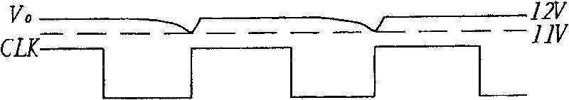
[0019] Since the charge pump uses capacitors to boost the DC voltage, it will inevitably cause slight ripples in the output waveform. The idea of ​​the present invention is to couple a stabilized voltage waveform to the output terminal of the charge pump, which is opposite to the ripple of the output voltage Vo of the charge pump, so that the waveform of the output voltage Vo is gentler, so as to improve the quality of power supply.

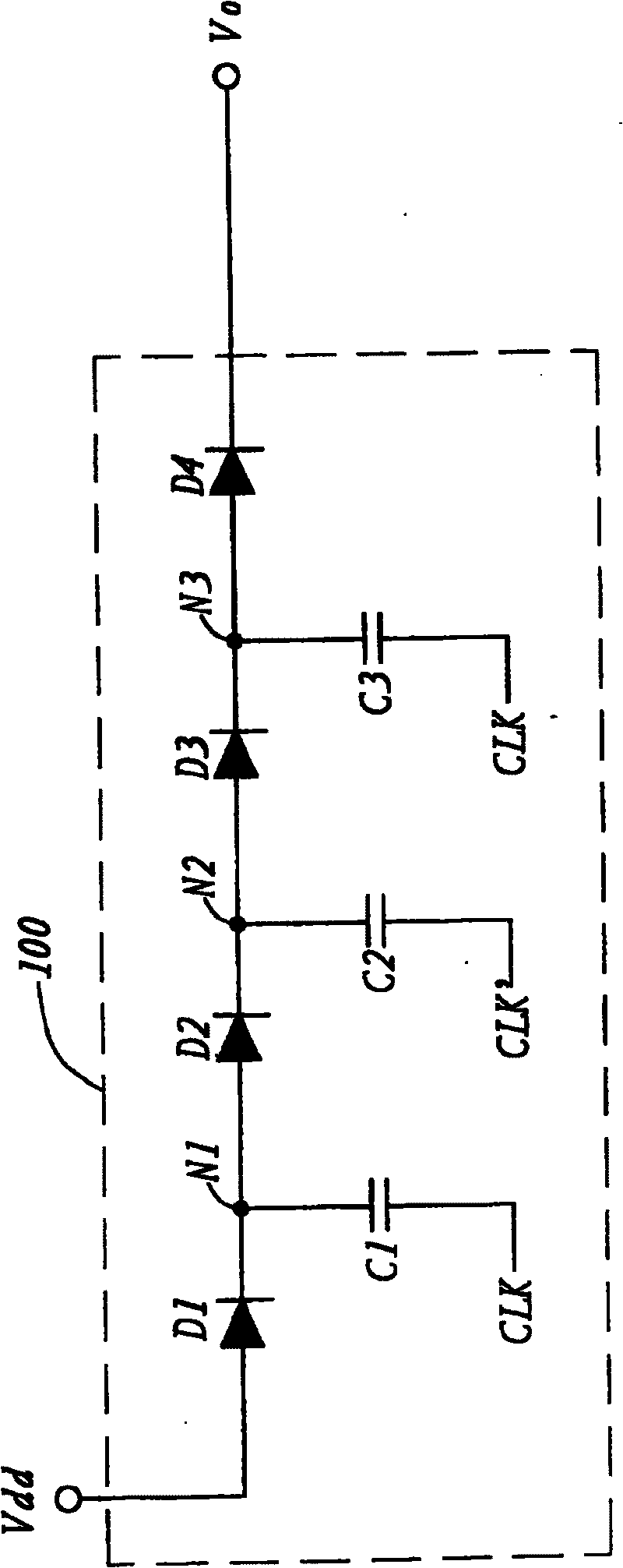
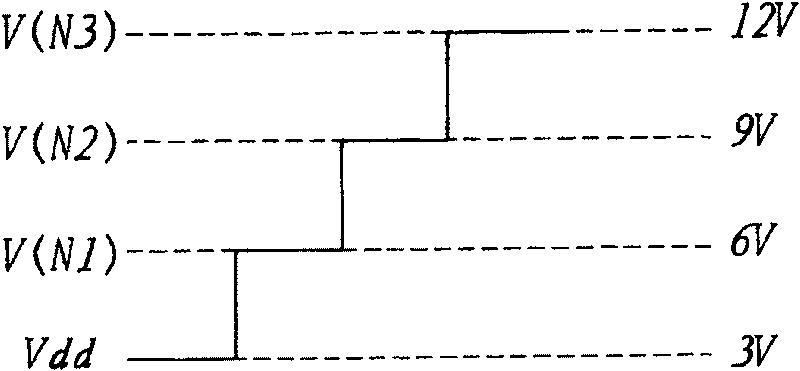
[0020] image 3 is a schematic diagram of a voltage stabilizing device coupled to a charge pump according to a preferred embodiment of the present invention. The charge pump in this example takes the two-phase charge pump 100 as an example. The voltage stabilizing device is coupled to the two-phase charge pump 100 . The charge pump 100 boosts the input voltage Vdd to an output voltage Vo according to the clock signal CLK. The voltage stabilizing device includes a voltage stabilizing capacitor Cs. One end of the voltage stabilizing capacitor C...


PUM


Abstract

The invention is a charge pump voltage stabilizer. The charge pump outputs a voltage according to a clock signal. The voltage stabilizer includes voltage-stabilizing capacitors, one end of each of which coupled with the output end of the charge pump and the other end receiving the reverse clock signal.

Description

technical field [0001] The present invention relates to a voltage stabilizing device, and in particular to a voltage stabilizing device for a charge pump. Background technique [0002] A charge pump can be used to boost the voltage. For example, in a rewritable flash memory, a low voltage is generally required for reading, such as 3V, and a high voltage is required for writing, such as 12V. However, the power supply voltage of a general integrated circuit chip is usually not high, such as 3V. If a working voltage greater than 3V is required, such as 12V, a charge pump can be used to increase the DC voltage. [0003] Traditional charge pumps include two-phase (2phase), four-phase (4phase) and so on. Here, a two-phase charge pump is taken as an example for illustration. figure 1 It is a schematic diagram of a traditional two-phase charge pump circuit. The two-phase charge pump 100 includes diodes D1, D2, D3, D4, capacitors C1, C2 and C3. For the convenience of description...

Claims


Application Information

Patent Timeline
IPC IPC(8): H02M3/06H02M1/14G05F3/08
Inventor 阙隆一林俞伸
Owner MACRONIX INT CO LTD
Features
  • R&D
  • Intellectual Property
  • Life Sciences
  • Materials
  • Tech Scout
  • Unparalleled Data Quality
  • Higher Quality Content
  • 60% Fewer Hallucinations
Learn More