
Locking type drill gripping head

A technology for drill chucks and locking discs, which is applied to the accessories of tool holders, pipes/pipe joints/fittings, turning equipment, etc., which can solve the problems of insufficient effective clamping and anti-loosening, and achieve reasonable structure, stable performance, The effect of easy assembly

Inactive Publication Date: 2005-01-26
SHANDONG WEIDA MASCH CO LTD
View PDF0 Cites 14 Cited by
  • Summary
  • Abstract
  • Description
  • Claims
  • Application Information

AI Technical Summary

Problems solved by technology

Existing drill chucks have obvious deficiencies in effective clamping and anti-loosening

Method used


Image

  • Locking type drill gripping head
  • Locking type drill gripping head
  • Locking type drill gripping head

Examples


Embodiment Construction

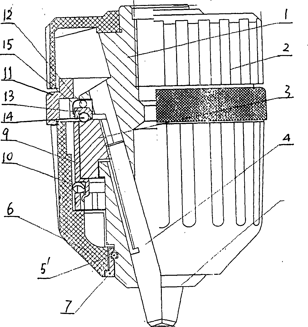
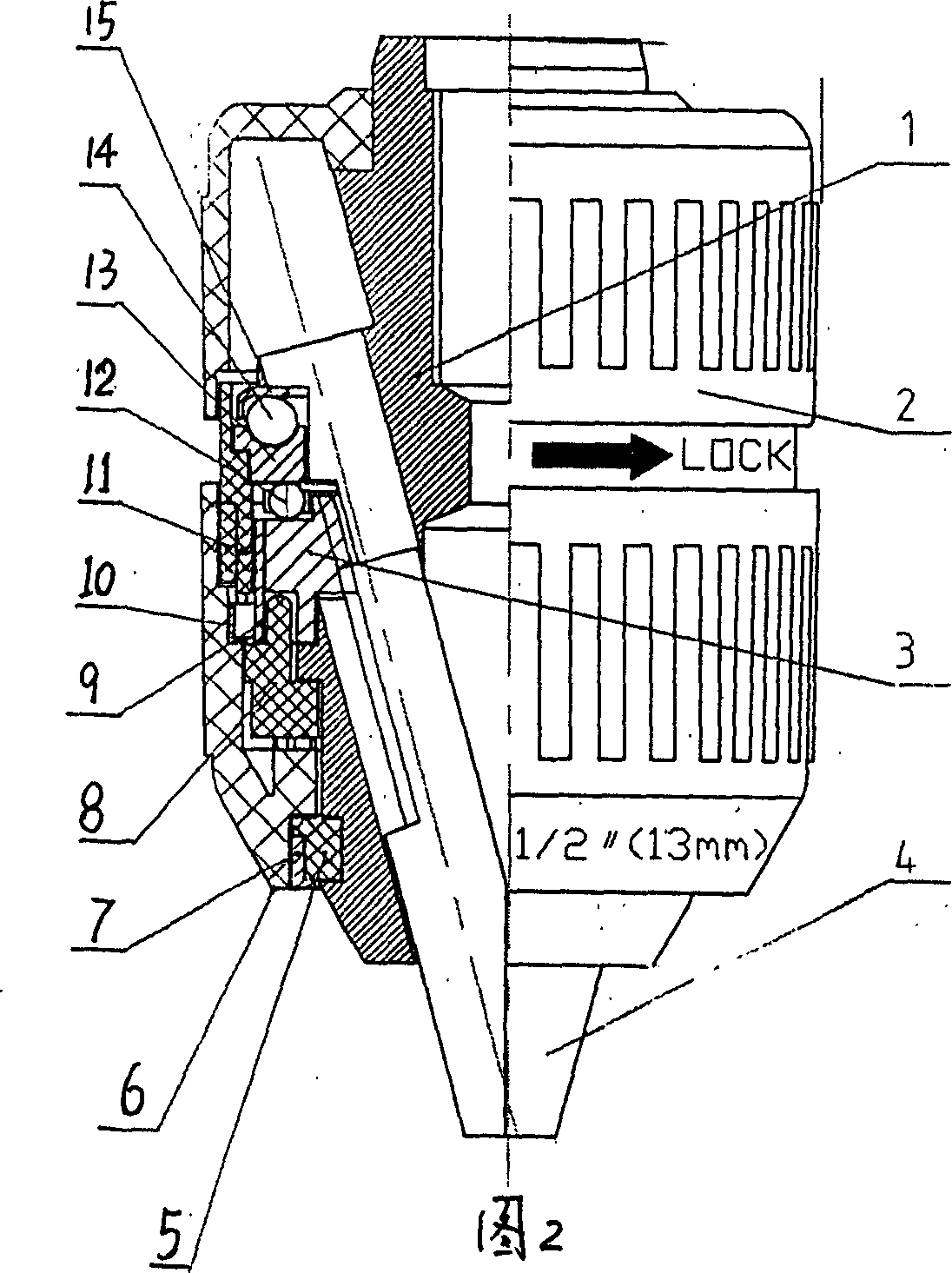
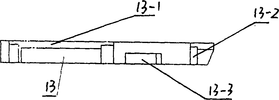
[0018] Such as figure 1 2. As shown in Figure 2, a locking drill chuck of the present invention includes a drill body 1, a clamping jaw 4, a nut 3, a front sleeve 6, a rear sleeve 2, a bearing 12, and the rear end of the drill body 1 is provided with The axial hole that the drive shaft of the drive tool engages with the rear sleeve 2 is connected and fixed by interference. The three clamping jaws 4 are respectively installed in the three equally divided oblique holes in the drill body 1, and the nut 3 is installed in the drill body. The clamping jaw 4 in the oblique hole engages, and the nut 3 is externally connected and fixed with a front sleeve 6, and a nut sleeve 9 can also be provided between the front sleeve 6 and the nut 3, which acts as a connecting drive. The above-mentioned composition, structure, and the relationship between the connected components belong to the prior art and will not be detailed here.

[0019] The feature of the present invention is that a locking sle...


PUM


Abstract

The invention relates to a locked drill chuck, including drilling body, clamp claw, silk screw, silk screw cover, the front cover, the back cover, the back end of the drilling body is arranged with an axial aperture connected to the driving tool, the external part is connected to the back cover. The three claws are assembled in the oblique apertures; the silk screw is engaged with the clamp claw in the oblique aperture. There has a locked cover between the front cover and the back cover. There has an elastic locking device made up of locking cap, rolling body, and locking plate between the drilling body surface and the silk screw. The locking plate has several concave slots, in which there arranges with rolling bodies, the elastic claw of the locking cap fixes the locking plate and several rolling bodies, and the locking cover is connected to the locking plate slots. The structure of the invention is reasonable, the locking function is strong, and the torque inputting efficiency is high.

Description

Technical field [0001] The invention relates to a drilling tool clamping device, in particular to a locking type drill chuck. Background technique [0002] As we know, the existing drill chuck is generally composed of a drill body, a clamping jaw, a nut, and an outer sleeve. The outer sleeve can include a front sleeve and a rear sleeve. The hand-tight chuck adds bearings and bearing pads to reduce friction. The back sleeve and the bearing pad are respectively interference-connected to the drill body, the three clamping jaws are respectively installed in three equally divided oblique holes on the drill body, the nut is installed in the nut groove of the drill body, and the nut and The thread on the clamping jaws cooperate to form a threaded transmission mechanism. A nut sleeve can also be provided outside the nut. The nut sleeve and the nut have an interference fit. The nut sleeve is provided with a front sleeve, and the inner wall of the front sleeve is provided with a key. The s...

Claims


Application Information

Patent Timeline
Patent Type & Authority Applications(China)
IPC IPC(8): B23B31/12
CPCB23B31/1238B23B2231/38Y10T279/17632
Inventor 杨桂模历彦兆
Owner SHANDONG WEIDA MASCH CO LTD
Learn More