Pulling device for gas pumping and draining drill rod

A gas pumping and drilling technology, which is applied to drill pipes, drill pipes, drilling equipment, etc., can solve the problems of economic loss, insufficient pulling force, and inability to increase the cross-sectional area.

Pending Publication Date: 2020-07-07
贵州能安机电设备制造有限公司
View PDF0 Cites 0 Cited by
  • Summary
  • Abstract
  • Description
  • Claims
  • Application Information

AI Technical Summary

Problems solved by technology

[0002] Tunnel drilling rigs for coal mines are important equipment for gas drainage in mine tunnels. After the drilling tools of the tunnel drilling rig complete the drilling, a certain force must be applied to pull out the drill pipe. The pulling force of the hydraulic cylinder of the rod is usually 15 tons. Due to the limitation of the size of the track, the cross-sectional area of ​​the hydraulic cylinder body cannot be increased. When the working pressure of the hydraulic system is constant, the pulling force generated by the hydraulic cylinder cannot be increased. , it is often encountered that when the drill pipe is pulled out, the resistance is large, but the pull-out force is not enough, which causes the drill pipe to get stuck in the wellbore and cannot be taken out, directly causing serious economic losses

Method used


Image

  • Pulling device for gas pumping and draining drill rod
  • Pulling device for gas pumping and draining drill rod
  • Pulling device for gas pumping and draining drill rod

Examples


Embodiment Construction

[0018] The technical solution of the present invention is further described below, but the scope of protection is not limited to the description.

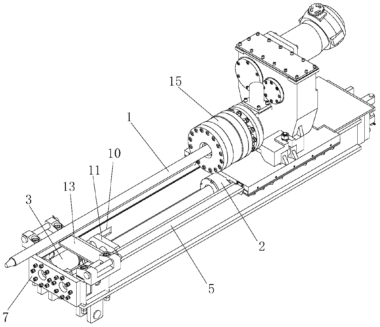
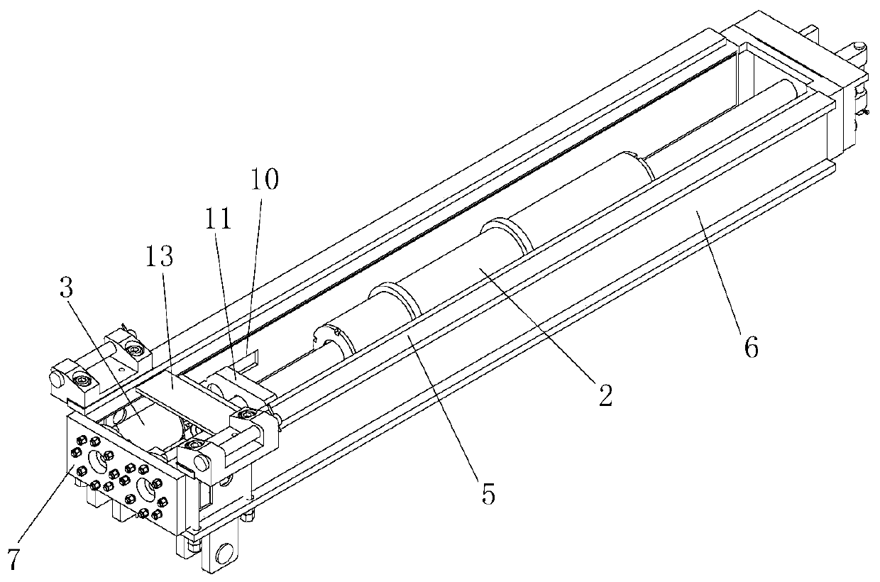
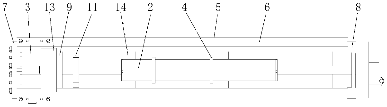
[0019] Such as Figure 1 to Figure 4 As shown, a lifting device for gas pumping and discharging drill pipes includes a main hydraulic cylinder 2 and a drawing hydraulic cylinder 3 for driving the movement of the drill pipe 1. The two ends of the piston rod of the main hydraulic cylinder 2 are fixed on the device, and the main hydraulic cylinder 2 The cylinder body of the hydraulic cylinder 2 can slide on its piston rod by pressurization, and then drive the drill pipe 1 to move; the drawing hydraulic cylinder 3 is fixed on the device, and the piston rod of the drawing hydraulic cylinder 3 can withstand the main hydraulic pressure when it is pushed out. The cylinder body of the cylinder 2 moves toward the pulling out direction of the drill pipe 1. When the drill pipe 1 is pulled out, the pulling hydraulic cylinder 3 and the main hydr...


PUM


Abstract

The invention provides a pulling device for a gas pumping and draining drill rod. The pulling device comprises a main hydraulic cylinder and a drawing hydraulic cylinder which are used for driving thedrill rod to move, wherein the two ends of a piston rod of the main hydraulic cylinder are fixed on the device; a cylinder body of the main hydraulic cylinder can slide on the piston rod of the mainhydraulic cylinder through pressurization; the drawing hydraulic cylinder is fixed on the device; and the piston rod of the drawing hydraulic cylinder is ejected out to be capable of propping againstthe cylinder body of the main hydraulic cylinder to move towards the pulling direction of the drill rod. According to the pulling device for the gas pumping and draining drill rod, the drawing hydraulic cylinder is arranged, so that the pulling force of the drill rod is increased, and the problem that the drill rod is blocked is solved.

Description

technical field [0001] The invention belongs to the technical field of tunnel drilling rigs, and in particular relates to a lifting device for gas pumping and discharging drill pipes on tunnel drilling rigs. Background technique [0002] Tunnel drilling rigs for coal mines are important equipment for gas drainage in mine tunnels. After the drilling tools of the tunnel drilling rig complete the drilling, a certain force must be applied to pull out the drill pipe. The hydraulic cylinder of the rod usually has a pulling force of 15 tons. Due to the limitation of the size of the track, the cross-sectional area of ​​the hydraulic cylinder body cannot be increased. When the working pressure of the hydraulic system is constant, the pulling force generated by the hydraulic cylinder cannot be increased. , It is often encountered that the pull-out resistance of the drill pipe is relatively large, but the pull-out force is insufficient, causing the drill pipe to be stuck in the wellbor...

Claims


Application Information

Patent Timeline
Patent Type & Authority Applications(China)
IPC IPC(8): E21B19/00E21B23/04
CPCE21B19/00E21B23/04
Inventor 罗太刚罗江田义飞黄佐泽谢威鄢红江
Owner 贵州能安机电设备制造有限公司
Why Eureka
Try Eureka