
Dynamic water velocity correction

A dynamic correction and velocity technology used in the field of geophysical exploration

Inactive Publication Date: 2005-01-26
WESTERNGECO SEISMIC HLDG LTD
View PDF0 Cites 3 Cited by
  • Summary
  • Abstract
  • Description
  • Claims
  • Application Information

AI Technical Summary

Problems solved by technology

Selecting Ideal Water Velocity for Seismic Data
Determining time from zero offset to bottom of water body for seismic data

Method used


Image

  • Dynamic water velocity correction
  • Dynamic water velocity correction
  • Dynamic water velocity correction

Examples


Embodiment Construction

[0023] The present invention will be described below in conjunction with preferred embodiments, but it should be understood that the present invention is not limited to these embodiments. On the contrary, the present invention should cover all alternatives, improvements and equivalents which are included within the essential scope defined by the claims of the present invention.

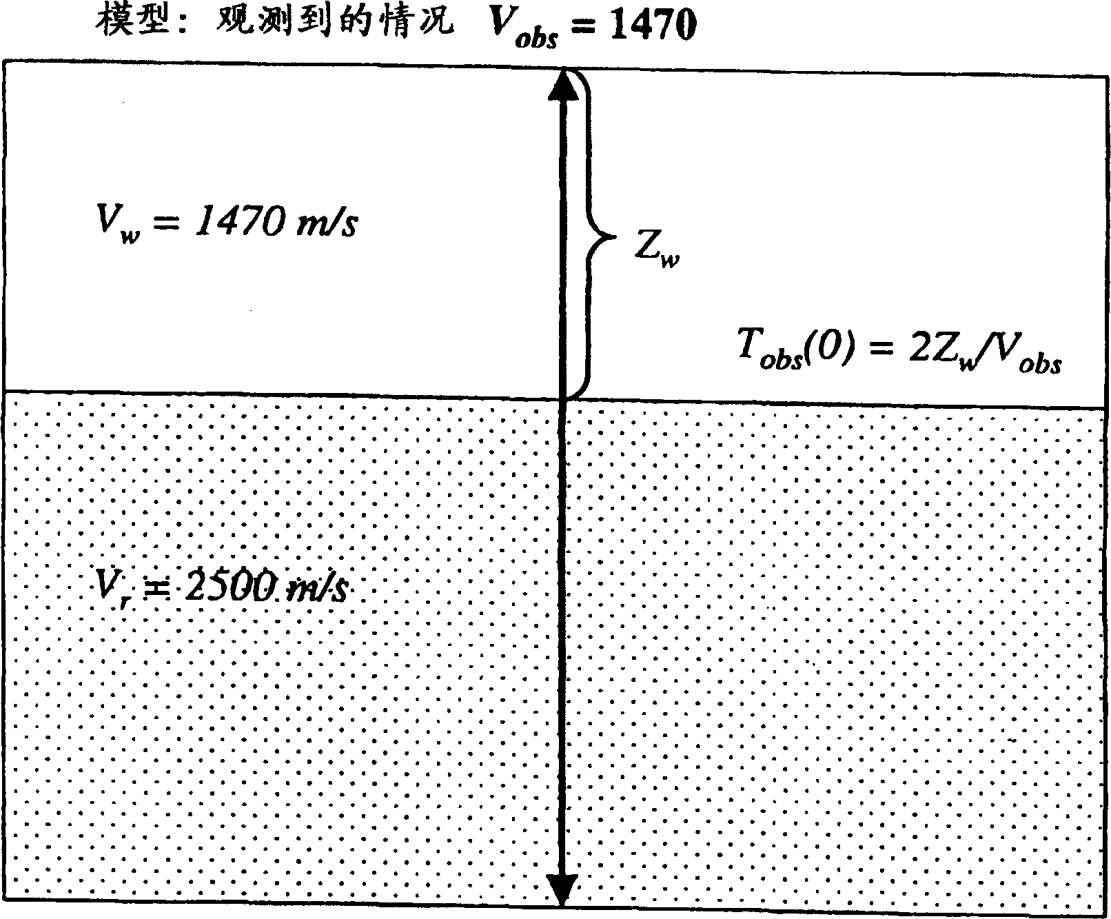
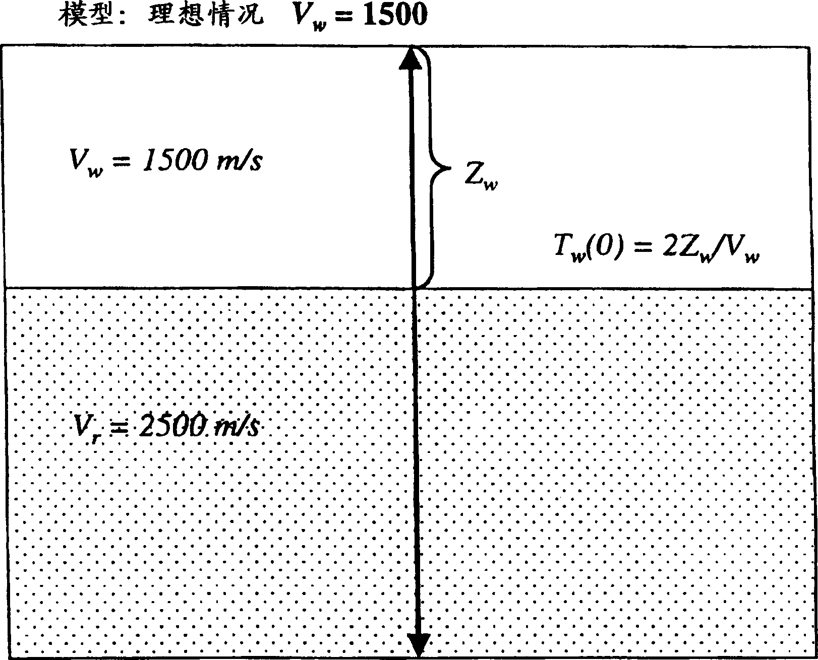
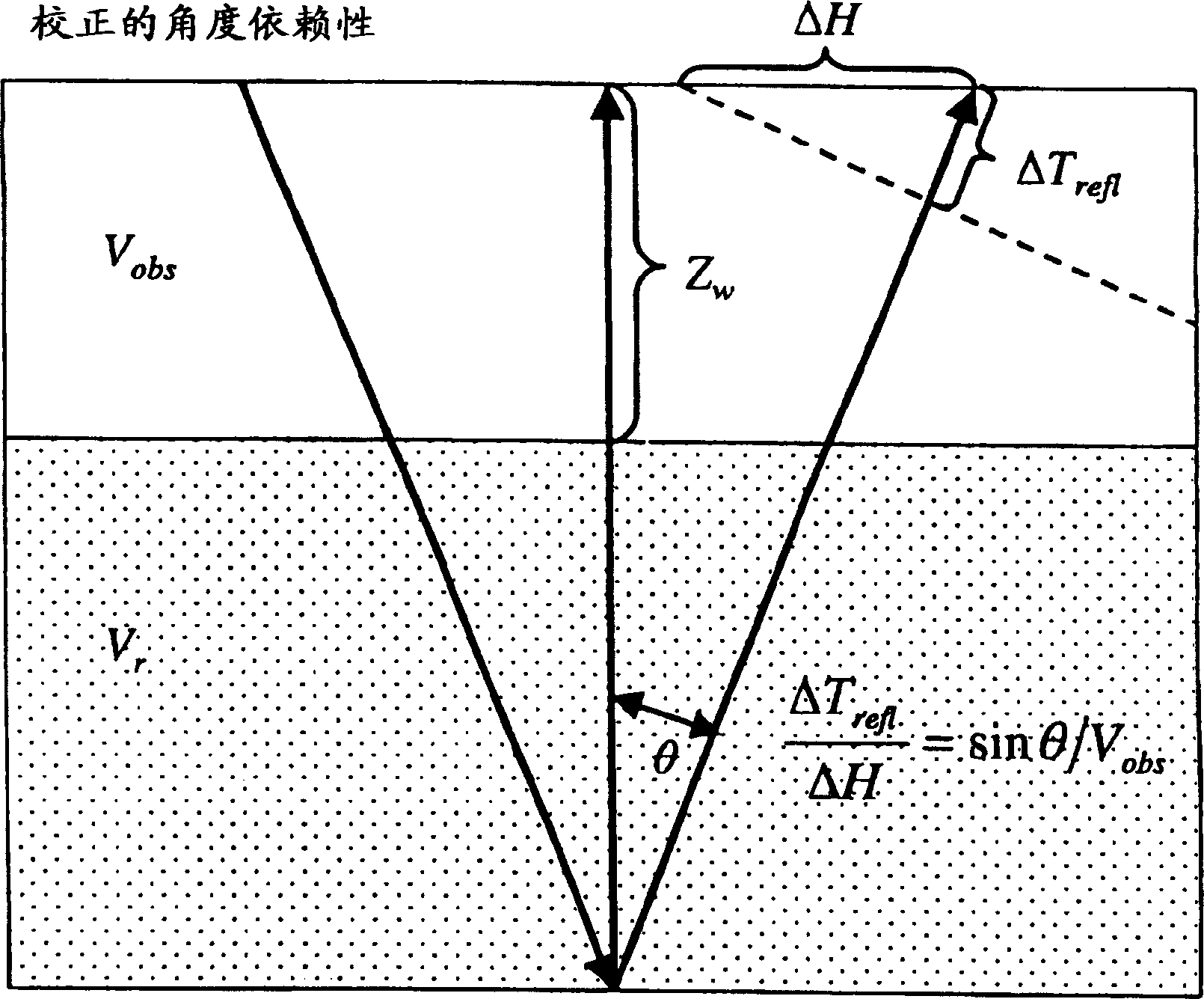
[0024] The present invention is a method of correcting seismic data for problems due to varying water velocities in marine data acquisition. In some embodiments, a correction is calculated and applied to map the seismic data to the ideal case of constant water velocity. Other advantages of the present invention will be apparent to those of ordinary skill in the art after reading this specification. To the extent that the following description is directed to particular embodiments and particular applications of the invention, it is illustrative only and should not be construed as limiting the scope of...


PUM


Abstract

This invention removes the effects of variable water velocity by calculating and applying corrections that map the seismic data to an ideal case of constant water velocity. All of the corrections assume, from a separate analysis step, that the vertical (zero-offset) timing errors induced by the water-velocity variations and that the zero-offset water bottom times are available. Equivalently, the water velocities are assumed known. The timing errors and water velocities are related. The zero-offset water-bottom times are also assumed available. From this information, and an arbitrarily-defined 'ideal' water velocity, it is possible to calculate an observed (actual) water velocity relative to the 'ideal' case. The only additional information needed is the angle of the ray path through the water layer. The angle may be calculated directly from normal moveout velocities derived from conventional analysis of the seismic data, and the information above. A time-dependent and offset-dependent correction may be derived for each sample of the seismic data prior to normal moveout correction.

Description

technical field [0001] The present invention relates to the field of geophysical prospecting, and more particularly to a method of calculating and applying a time correction to correct for the propagation of varying velocities through a water layer. Background technique [0002] In the oil and gas industry, geophysical prospecting techniques are widely used to aid in the search and evaluation of subsurface hydrocarbon deposits. Typically, a seismic energy source is used to generate seismic signals that propagate into the earth and are at least partially reflected by subsurface seismic reflectors (ie, interfaces between formations having different acoustic impedances). The reflections are recorded by seismic detectors located at or near the surface, at known depths in a body of water, or in a borehole, and the resulting seismic data can be processed to yield information about the location of subsurface reflectors and the physical properties of the formation. characteristic. ...

Claims


Application Information

Patent Timeline
IPC IPC(8): G01V1/00G01V1/36G01V1/38
CPCG01V1/38G01V1/362G01V2210/52
Inventor 斯科特·麦凯
Owner WESTERNGECO SEISMIC HLDG LTD
Learn More