

Heat exchanger
A technology of heat exchangers and fins, applied in the field of heat exchangers, can solve the problem of heat transfer reduction of heat exchangers, etc.
- Summary
- Abstract
- Description
- Claims
- Application Information
AI Technical Summary
Problems solved by technology
Method used
Image

Examples
no. 1 approach
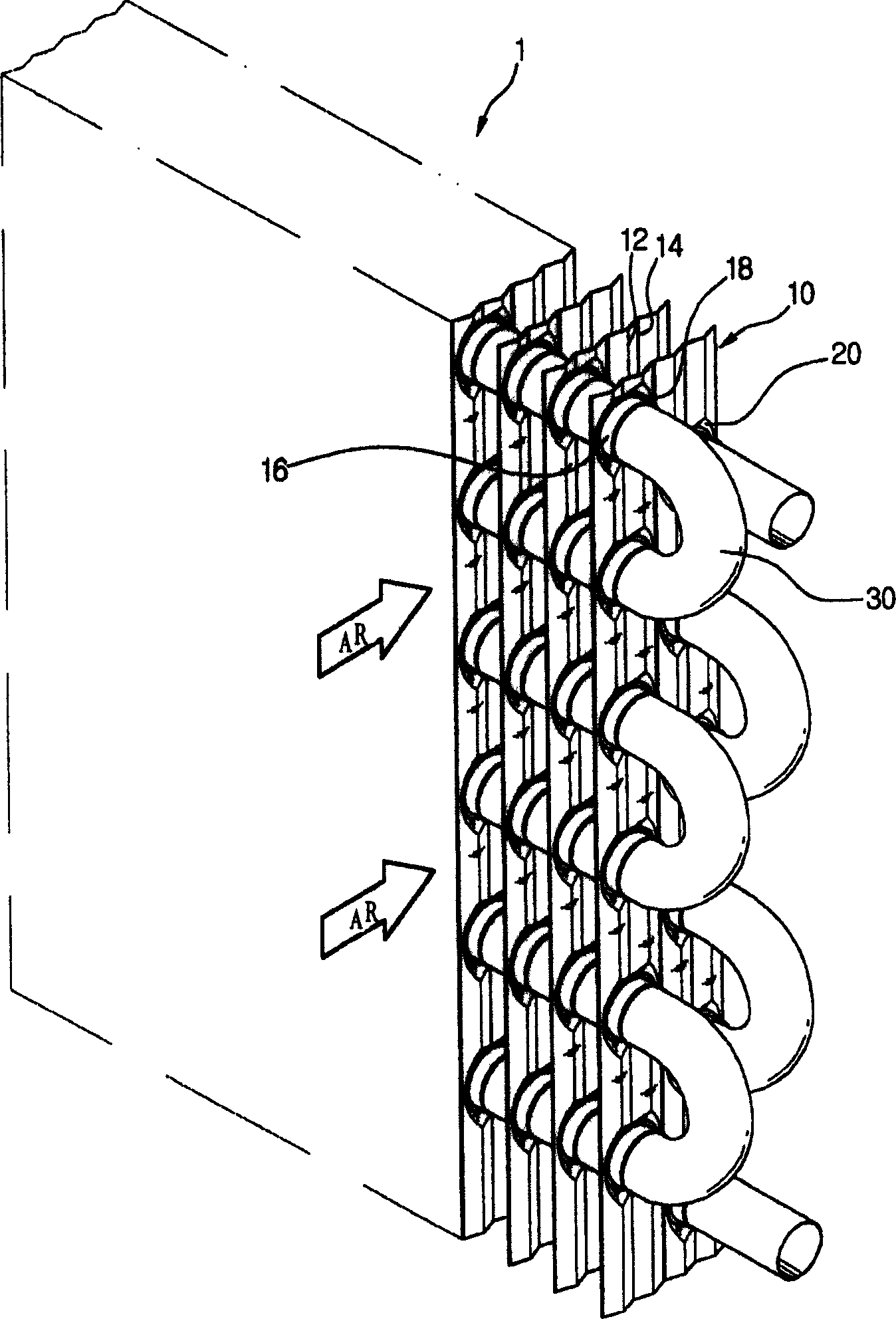
[0064] Figures 5 to 12 A first embodiment of the present invention is shown in which arrows AR indicate the direction of air flow.
[0065] refer to Figures 5 to 7 , The heat exchanger 101 according to the first embodiment of the present invention includes a plurality of fins 110 spaced apart from each other by a predetermined distance and a plurality of tubes 130 through the fins 110 at a vertical angle through which refrigerant flows.
[0066] In this embodiment, the fin 110 includes at least four peaks 112 and at least five valleys 114 inclined at a predetermined angle and continuously intersecting each other; forming a fin defining an insertion hole 116a through which the tube 130 passes vertically a collar 116; a base 118 for supporting the tube 130; and an inclined portion 120 inclined upward from the outer peripheral surface of the base 118 toward the peak 112.
[0067] In the fin 110, at least four peaks 112 (112a1, 112b, 112c, and 112d) and at least five valleys 1...
no. 2 approach
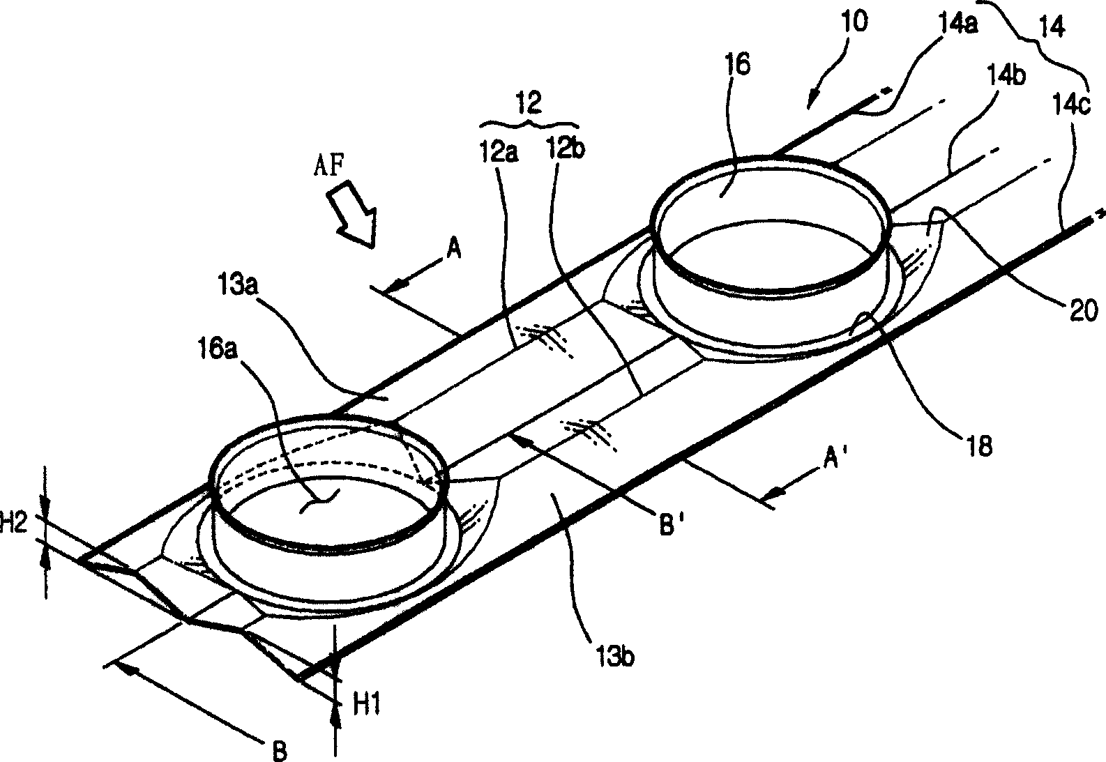
[0107] Figures 13 to 18 The second embodiment of the present invention is shown, and the arrow AR in the figure shows the air flow direction.
[0108] refer to Figure 13 , the fin 210 includes first and second peaks 212 (212a and 212b), and first, second and third valleys 214 (214a, 214b and 214c). The first and third valleys 214a and 214c are defined by the two side ends of the fins, and the second valley 214b is formed between the peaks 212a and 212b.
[0109] The first, second and third valley portions 214a, 214b and 214c are located on the same horizontal plane. The second valley portion 214b has a predetermined width.
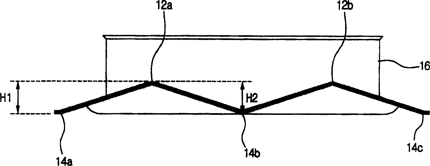
[0110] now refer to Figure 14 To describe in more detail, the peaks 212 and the valleys 214 are alternately arranged, and the heights H21 from the horizontal plane to the peaks 212 are the same as each other.
[0111] The second valley portion 214b is formed on the longitudinal central portion of the fin between the first and second peak lines 214a...
no. 3 approach
[0132] Figures 19 to 25 The third embodiment of the present invention is shown, and the arrow AR in the figure shows the air flow direction.
[0133] refer to Figures 19 to 2 1. The heat exchanger 301 includes: a plurality of fins 310, each of which has at least two peaks 312 and at least two valleys 314, which are arranged alternately; a plurality of tubes 330, which pass through the fins 310 at right angles fin collars 316 for fixing the tubes 330 inserted into the fins 310; bases 318 each formed around the outer peripheral lower end of each fin collar 316; The peak portion 312 is used to prevent the air flowing around the tube 330 from breaking away from the peripheral surface of the tube 330 .
[0134]The fins 310 are formed in a W shape to define three valleys 314 (314a, 314b and 314c) and two peaks 312 (312a and 312b) formed between the valleys 314a and 314b and 314b respectively. and 314c. The peaks 312a and 312b are located on the same horizontal plane. A depth ...
PUM
 Abstract
Description
Claims
Application Information