Planar luminescent illumination device including auxiliary electrode

A technology for auxiliary electrodes and light-emitting devices, which is applied in the field of light-emitting devices including auxiliary electrodes, and can solve problems such as insufficient suppression of uneven brightness

Inactive Publication Date: 2005-02-02
TOYOTA IND CORP
View PDF1 Cites 2 Cited by
  • Summary
  • Abstract
  • Description
  • Claims
  • Application Information

AI Technical Summary

Problems solved by technology

Therefore, auxiliary electrodes must be formed according to liquid crystal pixels, and uneven brightness cannot be sufficiently suppressed

Method used


Image

  • Planar luminescent illumination device including auxiliary electrode
  • Planar luminescent illumination device including auxiliary electrode
  • Planar luminescent illumination device including auxiliary electrode

Examples


no. 1 example

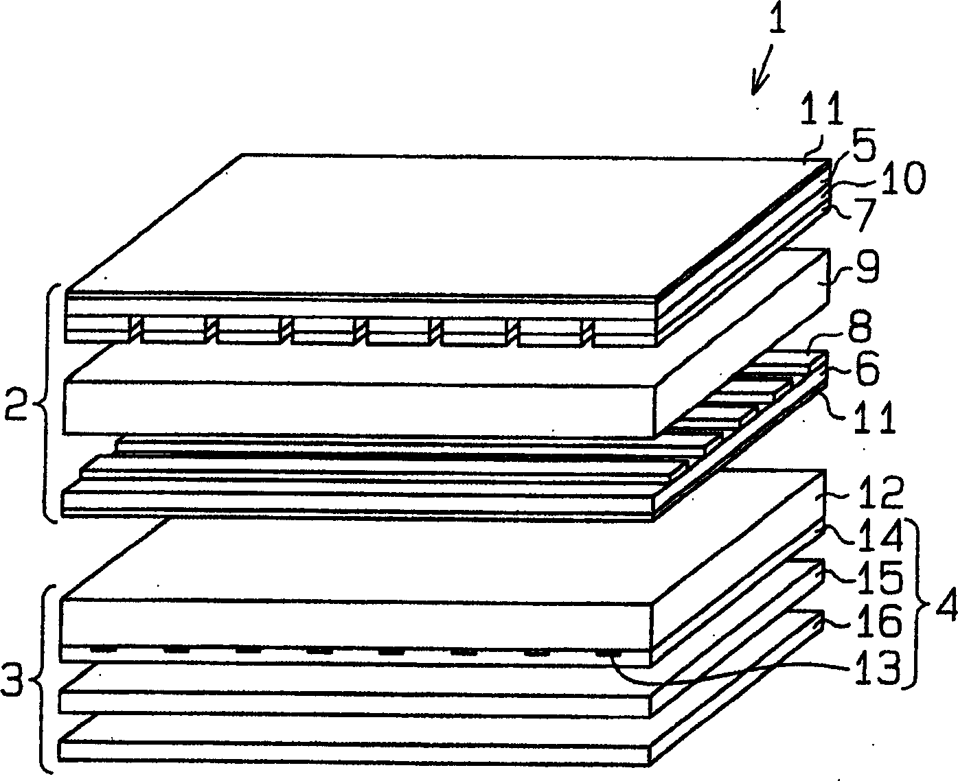
[0025] will refer to Figure 1~3 An organic electroluminescent device 3 according to a first embodiment of the present invention is described. The organic electroluminescent device 3 is used as a backlight for the passive matrix transmissive liquid crystal display 1 .

[0026] Such as figure 1 As shown, a transmissive liquid crystal display 1 includes a passive matrix liquid crystal panel 2 and an organic electroluminescent device 3 used as a surface emitting device.

[0027] A liquid crystal panel 2 , which is a known panel, includes a first transparent substrate 5 , a second transparent substrate 6 , and a liquid crystal layer 9 arranged between the first transparent substrate 5 and the second transparent substrate 6 .

[0028] Two polarizers 11 are arranged on the outer surface of the first transparent substrate 5 and the outer surface of the second transparent substrate 6, respectively.

[0029] A plurality of parallel stripes of color filters 10 are formed on the surfa...

no. 2 example

[0055] In a second embodiment of the invention, the organic electroluminescent device 33 of a passive matrix transmissive liquid crystal display 30 comprises a transparent substrate 31 with a planar light exit surface 34, such as Figure 4 shown. On the light exit surface 34 of the transparent substrate 31 is arranged a prism sheet, which is an optical sheet. In other respects, the structure of the liquid crystal display 30 is the same as that of the liquid crystal display 1 in the first embodiment.

[0056] At the portion of the prism sheet 32 ​​corresponding to the auxiliary electrode 13, parallel microprisms or protrusions 32a having a triangular cross section are formed.

[0057] The organic electroluminescent device 33 of the second embodiment has the same advantages as the organic electroluminescent device 3 of the first embodiment.

no. 3 example

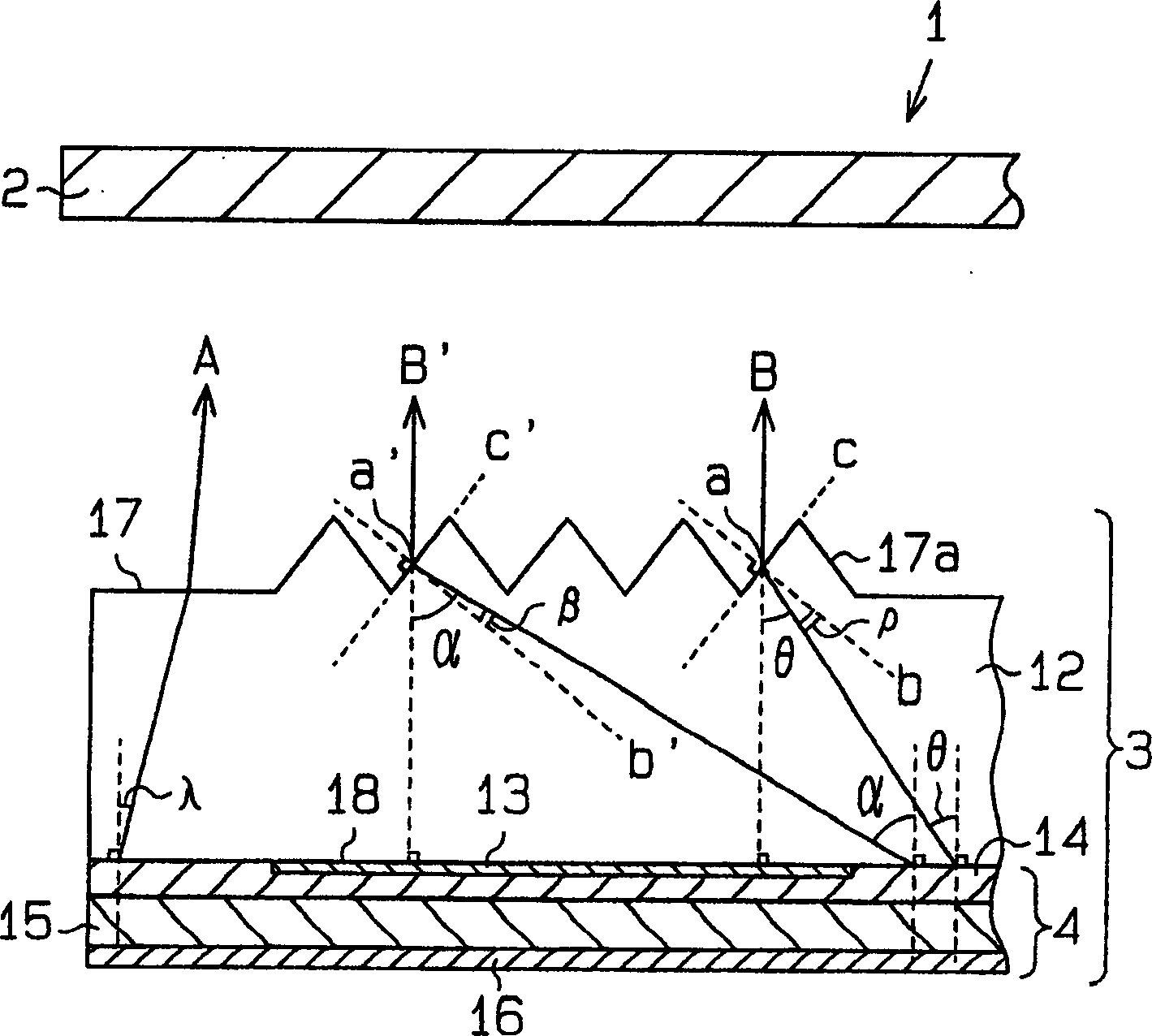
[0059] In a third embodiment of the present invention, an organic electroluminescent element 45 of an organic electroluminescent device 44 for a passive matrix transmissive liquid crystal display 40 includes an auxiliary electrode 43 . Such as Figure 5 As shown, on the surface of the auxiliary electrode 43 facing the transparent substrate 12, parallel microprisms or protrusions 43a having a triangular cross-section are formed. In other words, the auxiliary electrode 43 has an uneven surface. As for other parts, the structure of the liquid crystal display 40 is the same as that of the liquid crystal display 1 in the first embodiment.

[0060] The organic electroluminescent device 44 of the third embodiment has the following advantages in addition to the above advantages (1) and (2).

[0061] A protruding portion 43 a is formed on the surface of the auxiliary electrode 43 facing the transparent substrate 12 . Thus, the angle of light propagating in the transparent substrate ...


PUM


Abstract

A luminescent device (3) for reducing unevenness of brightness. The luminescent device includes a transparent substrate (12), which has a light exit surface (17) and an incident surface (18), and a luminescent element (4), which is formed on the incident surface of the transparent substrate. The luminescent element includes a transparent electrode (14) formed on the incident surface of the transparent substrate, an auxiliary electrode (13) formed on a part of the transparent electrode, and a thin-film layer (15), which is formed on the transparent electrode, for emitting light. The transparent substrate includes a projection (17a) formed on the light exit surface.

Description

technical field [0001] The present invention relates to a light emitting device, more particularly, to a light emitting device including an auxiliary electrode. Background technique [0002] In a display including a light emitting element like an organic electroluminescent element and a transparent electrode, the transparent electrode is mainly composed of, for example, indium tin oxide (ITO) or zinc oxide (ZnO). [0003] The conductivity of the transparent electrode is low. Thus, when a transparent electrode is used, there is a large difference in the resistance of the region near the connection terminal and the resistance of the region far from the connection terminal. This results in a large difference in the value of the current flowing through the region close to the connection terminal and the value of the current flowing through the region far from the connection terminal. The current value affects the light emission luminance of the organic electroluminescence elem...

Claims


Application Information

Patent Timeline
Patent Type & Authority Applications(China)
IPC IPC(8): H05B33/02G02F1/13357H01L27/32H01L51/50H05B33/26
CPCG02F1/133603G02F2201/122G02F2201/40G02F2203/03H01L27/3232H01L51/5212H01L51/5268H01L51/5275H10K59/50H10K50/814H10K50/854H10K50/858G02F1/1335
Inventor 加藤祥文稗田真人牟田光治
Owner TOYOTA IND CORP
Why Eureka
Try Eureka