
Micro actuator for controlling focal depth

A microcontroller, depth of focus technology, applied in instrumentation, head configuration/installation, optics, etc., which can solve problems such as power consumption, inability to achieve compact size, etc.

Active Publication Date: 2005-02-02
IONOSEP X HLDG
View PDF0 Cites 7 Cited by
  • Summary
  • Abstract
  • Description
  • Claims
  • Application Information

AI Technical Summary

Problems solved by technology

[0008] However, the conventional control of the depth of focus of a microcontroller is disadvantageous in that a compact size is hardly achievable and there is an additional power consumption
Therefore, it is not suitable for small-sized information storage devices

Method used


Image

  • Micro actuator for controlling focal depth
  • Micro actuator for controlling focal depth
  • Micro actuator for controlling focal depth

Examples


Embodiment Construction

[0027] Embodiments of the present invention will now be described in detail by way of examples illustrated in the accompanying drawings.

[0028] There are many possible embodiments for a microcontroller for controlling the depth of focus according to the present invention, the preferred embodiment will now be described.

[0029] The scope of the invention is not limited to the specific embodiments described below but can vary within the scope of the claims.

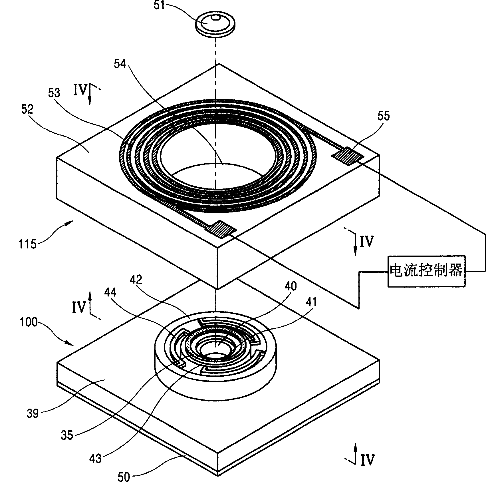
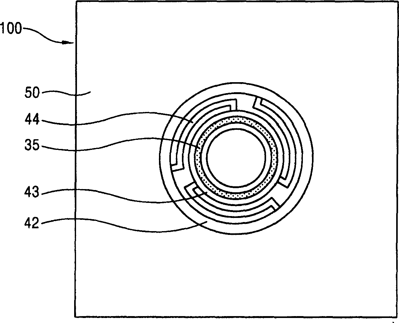
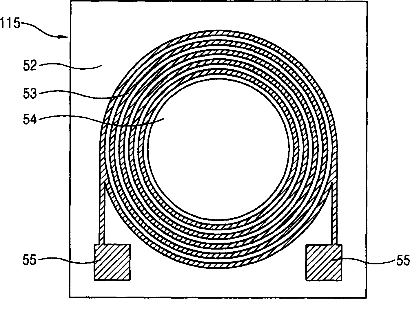
[0030] Figures 1 to 4 A microcontroller for controlling the depth of focus according to the first embodiment of the present invention will be described. in detail, figure 1 is a partially exploded schematic diagram illustrating a lens mounting part and a laminated coil for a microcontroller for controlling a depth of focus according to a first embodiment of the present invention, figure 2 is a plan view illustrating a lens mounting part according to a first embodiment of the present invention, image 3 is a plan v...


PUM


Abstract

A micro actuator for controlling a focal depth includes: a lens for forming a focal pint by focusing light coming from a light source; a lens mounting unit having a lens mounted therein and allowing the lens to move in one axial direction; and an electromagnetic force generator consisting of a constant magnetic field generating member having a magnetic field in a predetermined direction and an variable magnetic field generating member for changing direction and strength of a magnetic field according to direction and amount of a current, installed at and around the lens mounting unit and causing the lens to move in a direction of an electromagnetic force generated by interaction of the two magnetic field generating members. The micro actuator for controlling a focal depth can be fabricated in a ultra-compact size, available for a mass production, and has a fast response speed.

Description

technical field [0001] The present invention relates to a microcontroller for controlling the depth of focus, and more particularly to a microcontroller for controlling the depth of focus capable of precisely controlling the depth of focus of a lens focusing light. Background technique [0002] In the case of an optical information recording and reproducing device using a rotating optical disc as a recording and reproducing medium, due to the flatness error of the optical disc, the mechanical vibration and the eccentricity error of the motor rotating the optical disc, the recording and reproducing layer of the optical disc and the optical disc pickup device The distance between the lenses is constantly changing. Such variations deteriorate the signal-to-noise ratio of recorded and reproduced optical signals, limit the readable and recordable bit size, and cause misreads and misrecords. Therefore, in order to precisely focus the input light onto the recording and reproductio...

Claims


Application Information

Patent Timeline
Patent Type & Authority Applications(China)
IPC IPC(8): G02B26/08
CPCG02B26/0875
Inventor 金声赫池昌炫李泳柱
Owner IONOSEP X HLDG
Learn More