Road-bridge changeover portion subgrade settlement test platform

A technology of test platform and transition section, which is applied in the test of basic structures, roads, bridges, etc., can solve the problems of lack of test equipment and experimental devices, and achieve the effect of wide application range, large scale and large settlement value.

Inactive Publication Date: 2005-02-16
CHANGAN UNIV
View PDF2 Cites 15 Cited by
  • Summary
  • Abstract
  • Description
  • Claims
  • Application Information

AI Technical Summary

Problems solved by technology

Some people in China have also carried out research work in this area, and actively promoted and applied it in engineering, and proposed some treatment methods, but there is no testing equipment and experimental equipment

Method used


Image

  • Road-bridge changeover portion subgrade settlement test platform
  • Road-bridge changeover portion subgrade settlement test platform
  • Road-bridge changeover portion subgrade settlement test platform

Examples


Embodiment 1

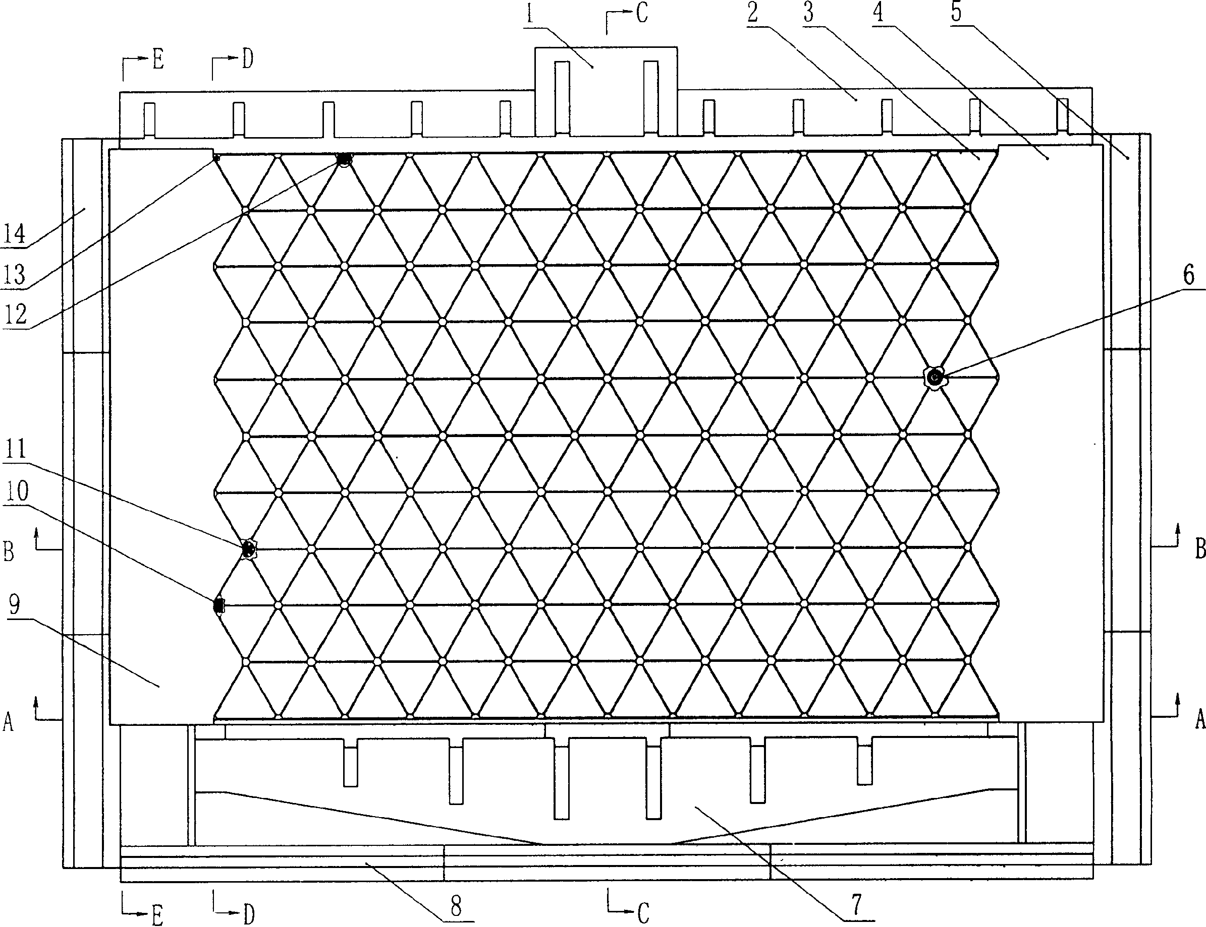
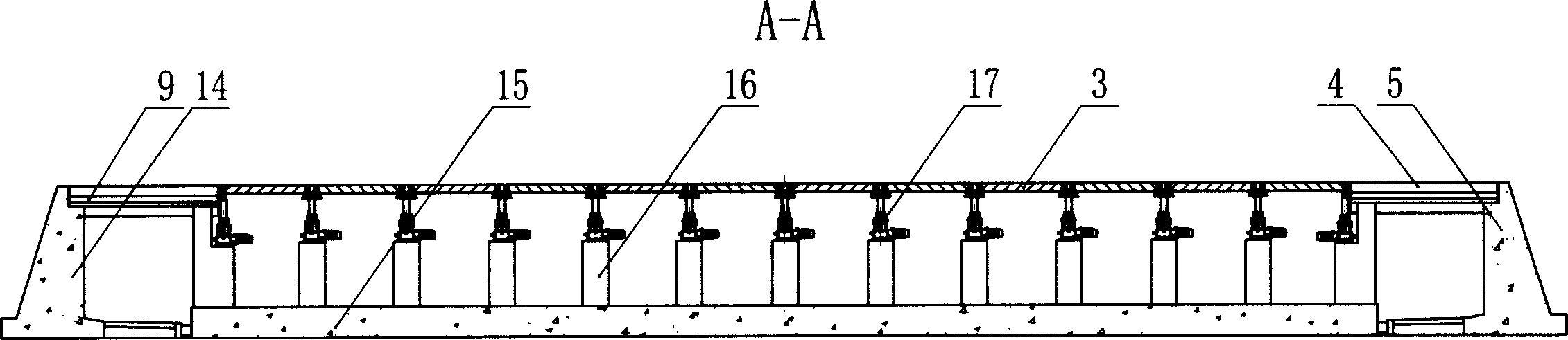
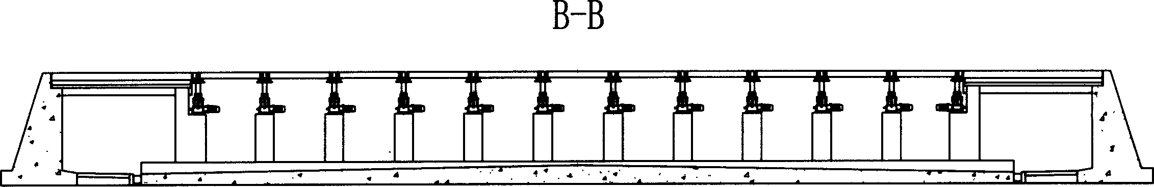
[0033] exist Figure 1~6 Among them, the subgrade settlement test platform of the road-bridge transition section in this embodiment is composed of a ribbed abutment 1, a front retaining wall 2, a movable settlement plate 3, a right cement concrete panel 4, a right retaining wall 5, and a six-point platform support 6 , gravity abutment 7, rear retaining wall 8, left cement concrete panel 9, two-point platform support 10, four-point platform support 11, three-point platform support 12, one-point platform support 13, left Side retaining wall 14, foundation stratum 15, column 16, electric manual jack 17 form.

[0034] The left side retaining wall 14 and the right retaining wall 5 are built on the left side of the foundation stratum 15, and a ribbed abutment 1 is built in the front middle of the foundation stratum 15, and the two sides of the front side ribbed abutment 1 The front retaining wall 2 is built on the side, the gravity abutment 7 is built on the back side of the founda...

Embodiment 2

[0044] In this embodiment, 189 upright columns 16 are built on the base layer 15, an electric manual jack 17 is placed on the upper end of each upright column 16, and a platform support is placed on the upper end of each electric manual jack 17 324 active settling plates 3 are placed on the platform support, each active settling plate 3 is a concrete equilateral triangle plate with a side length of 154cm, and the thickness of the active settling plate 3 is 12cm. Other components and the coupling relationship of the components are the same as in Embodiment 1.

Embodiment 3

[0046]In this embodiment, 95 upright columns 16 are built on the base layer 15, an electric manual jack 17 is placed on the upper end of each upright column 16, and a platform support is placed on the upper end of each electric manual jack 17 152 active settling plates 3 are placed on the platform support, each active settling plate 3 is a concrete equilateral triangle plate with a side length of 231cm, and the thickness of the active settling plate 3 is 22cm. Other components and the coupling relationship of the components are the same as in Embodiment 1.


PUM

PropertyMeasurementUnit
Side lengthaaaaaaaaaa
Thicknessaaaaaaaaaa
Side lengthaaaaaaaaaa

Abstract

A road-bridge transition section roadbed settlement test platform includes a left retaining wall at the left of the foundation stratum, a right retaining wall at the right, ribbed panel bridge abutment at the front, a front retaining wall and a gravity bridge abutment and a rear retaining wall, at least 95 uprights are set on the foundation stratum with a jack on each top, a support supporting a movable settlement plate is set at the top of the jack, a left concrete panel is set on the left of the top surface, and a right cement concrete panel is set at the right between the right and left retaining walls. The test plat form is connected with computer and power control system by cables to timely control its settlement, rate and its final settlement curves.

Description

technical field [0001] The invention belongs to the technical field of auxiliary equipment for building, repairing, repairing or demolishing roads or similar pavements, and in particular relates to equipment or devices for veneering, which can measure the shape of the pavement and add materials in proportion to the measured unevenness of the pavement device of. Background technique [0002] The road-bridge transition section is a high-incidence area for road diseases, and "jumping at the bridge head" is an intuitive manifestation of this disease. The "jumping at the bridge head" phenomenon in the expressway not only greatly affects the comfort of driving, but also reduces the traffic capacity of the road. Moreover, it is one of the important hidden dangers of road traffic safety, which has seriously affected the social image and social benefits of expressways. [0003] Over 10,000 kilometers of highways have been built in the country, and the phenomenon of "jumping vehicles...

Claims


Application Information

Patent Timeline
IPC IPC(8): E01C23/01E01D19/02E02D33/00
Inventor 谢永利张宏光杨晓华刘保健郁录平申汝涛俞永华
Owner CHANGAN UNIV
Why Eureka
Try Eureka