
Active matrix liquid crystal display panel driving method

A liquid crystal display panel and active matrix technology, applied in transistors, static indicators, instruments, etc., can solve problems such as blurred pictures and achieve the effect of improving picture quality

Inactive Publication Date: 2005-02-16
HONG FU JIN PRECISION IND (SHENZHEN) CO LTD +1
View PDF0 Cites 1 Cited by
  • Summary
  • Abstract
  • Description
  • Claims
  • Application Information

AI Technical Summary

Problems solved by technology

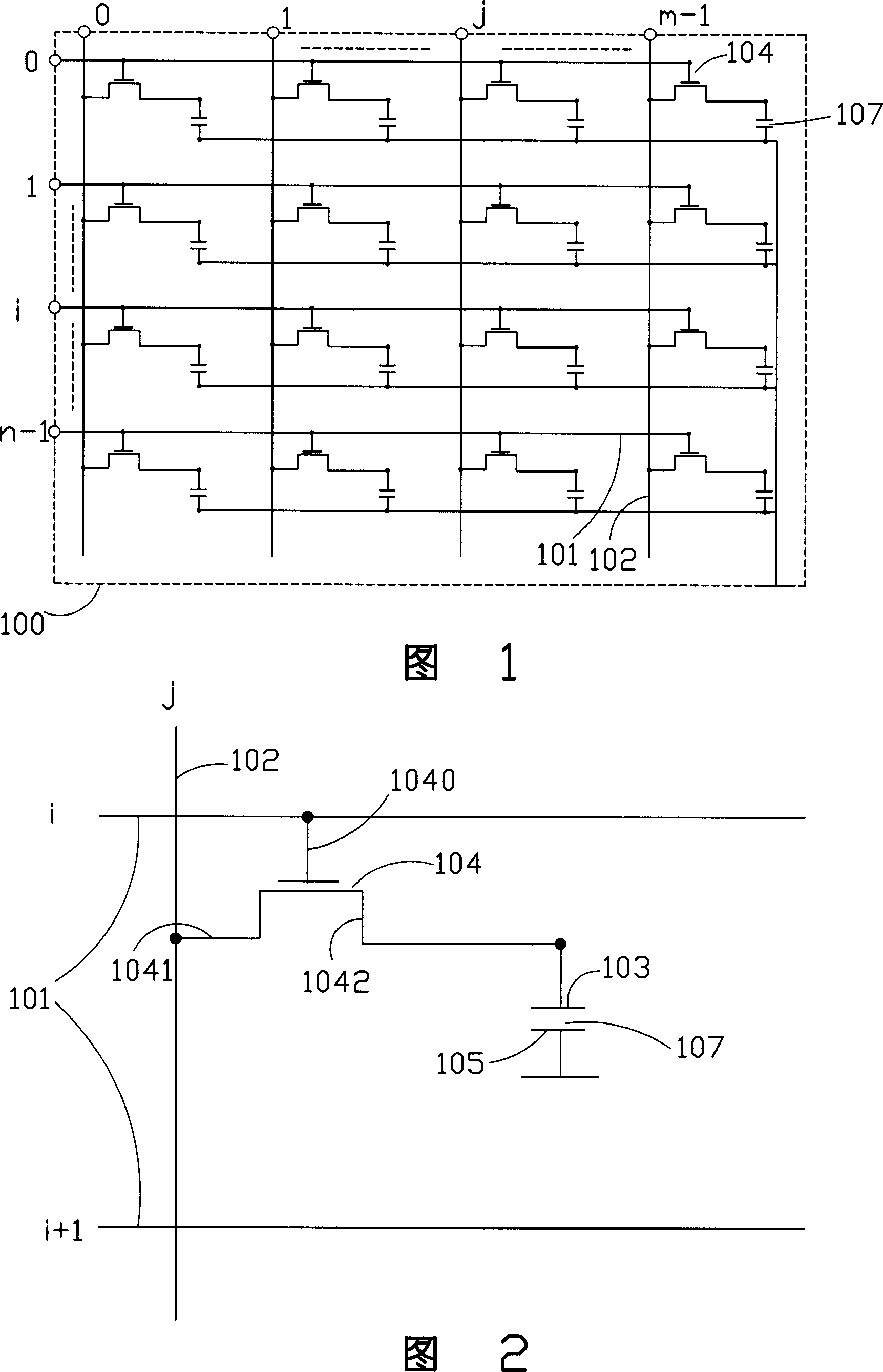
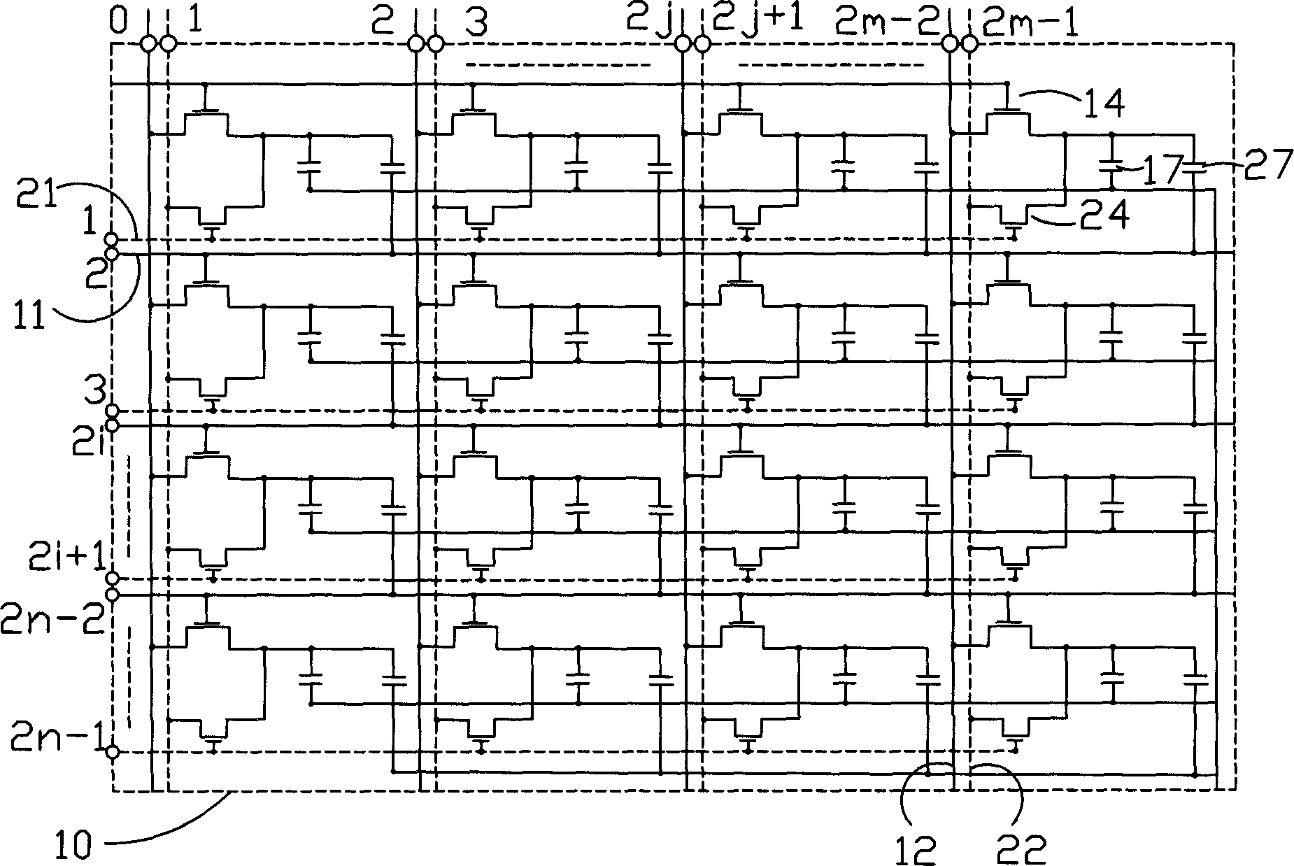
[0008] In order to overcome the defect in the prior art that the picture is blurred during dynamic display due to the slow response of the liquid crystal, the present invention provides an active matrix liquid crystal display unit with two TFT structures that can make the liquid crystal respond quickly and display the picture clearly. Driving method of display panel

Method used


Image

  • Active matrix liquid crystal display panel driving method
  • Active matrix liquid crystal display panel driving method
  • Active matrix liquid crystal display panel driving method

Examples


Embodiment Construction

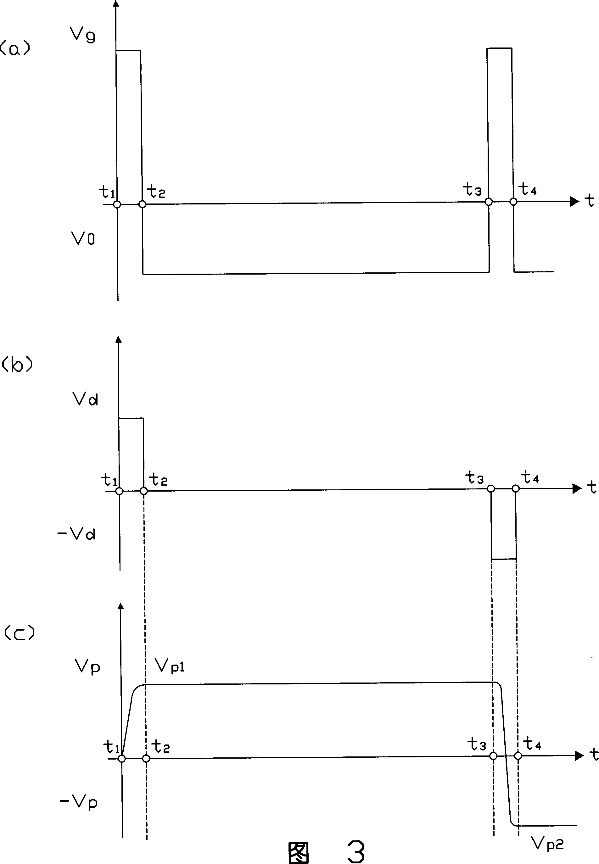
[0025] see Image 6 and Figure 7, the present invention adopts Figure 4 with Figure 5 The driving waveform diagram of the active matrix liquid crystal display panel driving method with two TFT structures, please refer to Image 6 (a), (b) are the gate and source signal waveform diagrams of TFT 14 respectively, and Fig. 7 (a), (b) and (c) are respectively the grid gate of TFT 24, the signal waveform diagram of source and pixel Voltage waveform diagram of electrode 13. The gate driving device (not shown in the figure) provides the first scanning voltage V G Driving the gate 140 of the TFT 14 to provide the second scanning voltage V G The gate 240 of the TFT 24 is driven, and the source driver (not shown) provides a first signal voltage V D1 Drive the source 141 of TFT 14 to provide the second signal voltage V D2 driving the source 241 of the TFT 24, the first signal voltage V D1 The size of the liquid crystal can not be deformed so that the picture is displayed in a brig...


PUM


Abstract

In the invention, one display unit possesses structure of two thin film transistors (TFT). First scanning voltage is provided for multiple first scanning lines to drive grids of multiple first TFTs. First signal voltage provided on multiple first signal lines is utilized to drive source poles of multiple TFTs. second signal voltage provided on multiple second scanning lines is utilized to drive grids of multiple second TFTs. Second signal voltage provided on multiple second signal lines is utilized to drive sources of multiple second TFTs. moment of providing second scanning voltage and second signal time is identical to or delayed to moment of providing second scanning voltage and second signal time.

Description

【Technical field】 [0001] The present invention relates to a driving method of a matrix liquid crystal display panel, in particular to a driving method of an active matrix liquid crystal display panel with a display unit having two TFT structures. 【Background technique】 [0002] Due to the advantages of lightness, thinness, and low power consumption, liquid crystal displays are widely used in modern information equipment such as televisions, notebooks, computers, mobile phones, and personal digital assistants. At present, the application of liquid crystal displays in the TV market is becoming more and more important. However, liquid crystal itself is a material with a viscosity coefficient, so its response speed cannot compete with CRT (Cathode-ray tube, cathode ray tube). In an active matrix liquid crystal display, except for the on and off time of the active element, the response time required for the liquid crystal molecules to switch in the gray scale needs to be less tha...

Claims


Application Information

Patent Timeline
Patent Type & Authority Applications(China)
IPC IPC(8): G09G3/36H01L29/786
Inventor 陈鹊如谢朝桦杨秋莲彭家鹏
Owner HONG FU JIN PRECISION IND (SHENZHEN) CO LTD
Learn More