Packet switching network distributed adaptive dither buffer adjusting method

A technology of packet switching network and adjustment method, which is applied in the field of distributed adaptive jitter buffer adjustment of packet switching network, and can solve the problems of wasteful use of jitter buffer, large queuing delay, etc.

Active Publication Date: 2005-02-16
ALCATEL LUCENT SHANGHAI BELL CO LTD
View PDF2 Cites 14 Cited by
  • Summary
  • Abstract
  • Description
  • Claims
  • Application Information

AI Technical Summary

Problems solved by technology

Since the maximum delay jitter introduced by packet switching networks is usually unpredictable, in order to absorb the maximum delay jitter and avoid jitter buffer overflow, the jitter b

Method used


Image

  • Packet switching network distributed adaptive dither buffer adjusting method
  • Packet switching network distributed adaptive dither buffer adjusting method
  • Packet switching network distributed adaptive dither buffer adjusting method

Examples


Embodiment Construction

[0031] The present invention will be further described in detail below in conjunction with the embodiments shown in the accompanying drawings.

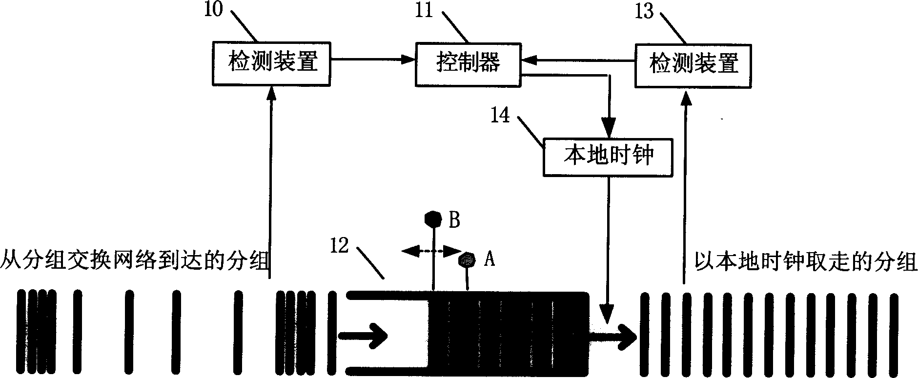
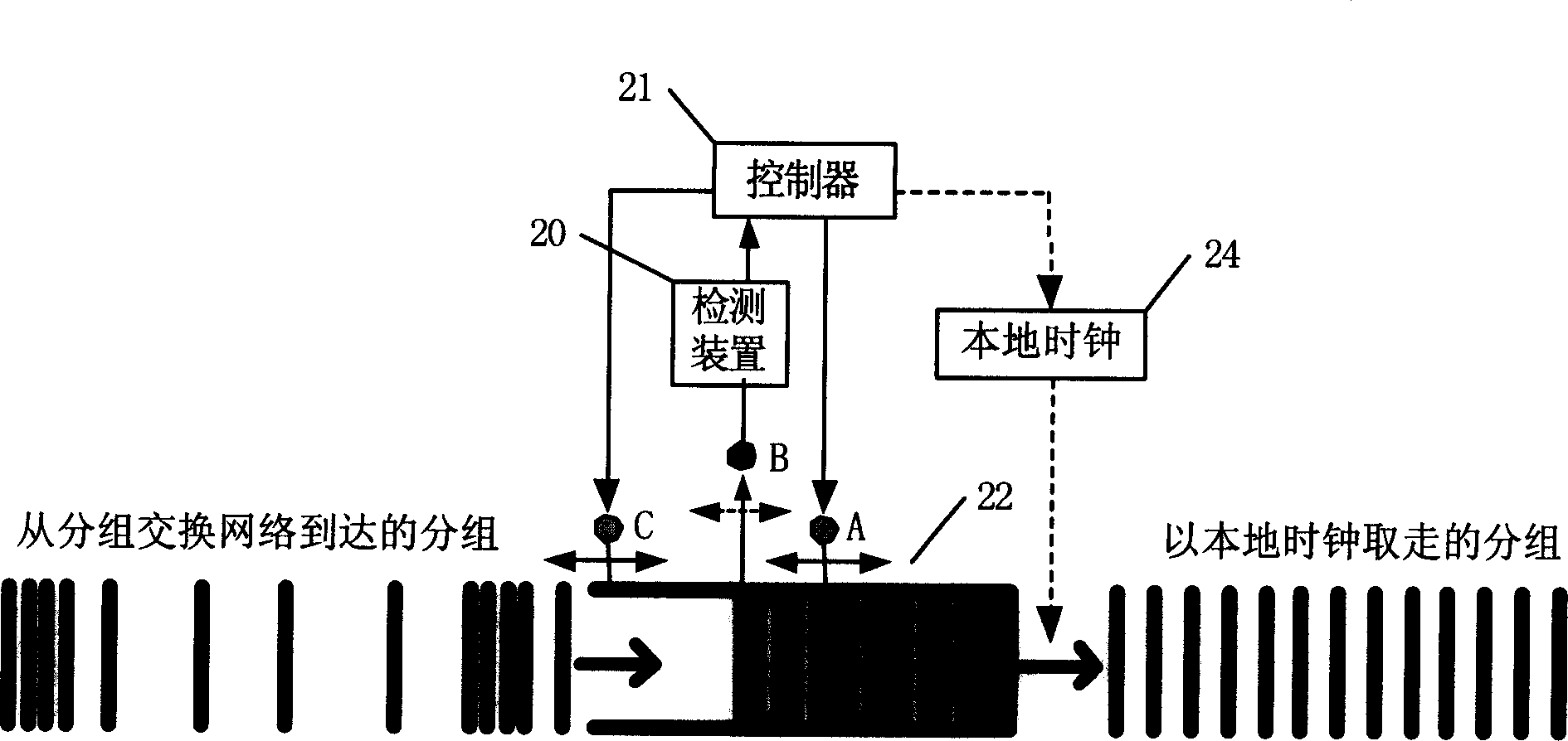
[0032] Figure 4 It is a schematic diagram of the distributed adaptive jitter buffer adjustment of the present invention, which includes communication devices 100 and 200 for two-way communication through the packet switching network 300, and the jitter buffers 122 and 222 in the illustration are the data reception jitter of the communication devices 100 and 200 respectively The buffer, the encapsulation and sending part of the sent data are not marked in the figure. Taking the jitter buffer 122 of the communication device 100 as an example, the detection device 120 periodically samples the fill level B of the jitter buffer, and the controller 121 samples the sampled value φ mR (i) processing to obtain a prediction of the trend of the local jitter buffer fill level variation and feed back the predicted value to the data sending end...


PUM


Abstract

Sampling filling level in local jitter buffer area in adjustment cycle of jitter buffer area, and processing the sampled sequence obtains predicted value for reflecting change trend of filling level in local jitter buffer area in the adjustment cycle. Further, considering change information of jitter buffer area feedback from data sending end synthetically obtains best estimation of state of local jitter buffer area, based on which, the optimal state is adjusted. Comparing with prior art, the invention adjusts a buffer area to an optimal are quicker since considering information in local jitter buffer area and in jitter buffer area at sending end. The invention speeds up convergence of adjustment procedure.

Description

(1) Technical field [0001] The invention relates to a distributed adaptive jitter buffer adjustment method of a packet switching network, in particular to a distributed adaptive jitter buffer adjustment method based on distributed jitter buffer measurement. (2) Background technology [0002] At present, the packet switching network has the advantages of cheap price, flexible protocol, good scalability, and mature technology, and has been widely used. Many real-time services, such as IP telephony, TDM (Time Division Multiplexing) circuit emulation services, etc. have been or will be tried to be transmitted on the packet switching network. The packet-switching network adopts asynchronous transmission mode, and most real-time services require end-to-end clock synchronization, requiring the clock at the receiving end to be consistent with the clock at the sending end. When the clocks of the receiving end and the sending end are not obtained from the same common clock synchroniz...

Claims


Application Information

Patent Timeline
IPC IPC(8): H04L49/9023
Inventor 刘儿兀沈钢金珊桂洛宁
Owner ALCATEL LUCENT SHANGHAI BELL CO LTD
Why Eureka
Try Eureka