
Automotive floor panel structure

A body floor and panel technology, which is applied to the superstructure, substructure, vehicle components, etc., can solve the problems of increased resonance frequency, increased cost, increased vehicle weight, etc., and achieves the effect of reducing acoustic emission and reducing noise.

Inactive Publication Date: 2005-02-23
MAZDA MOTOR CORP
View PDF1 Cites 3 Cited by
  • Summary
  • Abstract
  • Description
  • Claims
  • Application Information

AI Technical Summary

Problems solved by technology

[0008] However, as described above, in the conventional case where the vibration-damping material and the vibration-proof material are fixed on the entire surface of the floor panel, there are problems of increased material cost and increased vehicle weight.
In addition, if the thickness of the floor panels increases, there is also the problem of increased vehicle weight.
[0009] In addition, with the floor panel structure described in the above-mentioned Japanese Patent Unexamined Publication, for example, in order to generate vibration in the 2×1 mode, the vibration region of the floor panel must have an approximately 2×1 rectangular shape, but since parts are placed Under the vehicle floor including drive shafts, differentials and other drive train components, suspension and other suspension system components, exhaust pipes, mufflers and other exhaust system components, and fuel tanks, and also because of the distance between seats in the passenger compartment In relation to each other, the layout of the frame elements is limited, so that the floor panel connected to the frame elements cannot be in a roughly 2×1 rectangular shape, and therefore there is a problem that it is impossible to create Vibration in ×1 mode
[0010] On the other hand, when the vibration area of ​​the floor panel is not approximately 2×1 rectangular shape, it is conceivable to form a rectangular vibration area by means of high rigidity bead or the like to form a 2×1 vibration area, but if the plate of the floor panel If the stiffness of the parts is very high or the vibration area is narrow, the original resonance frequency of the floor panel itself is very high. If this bead is set on such a floor panel, the stiffness of the floor panel will be greatly improved, and the resonance frequency will be lower. It is further increased, so that the vibration of the 2×1 mode is generated in a frequency band higher than 250Hz, so there is a problem that it is impossible to generate a 2×1 mode in a frequency of 250Hz close to the road noise generated by resonance in the tire
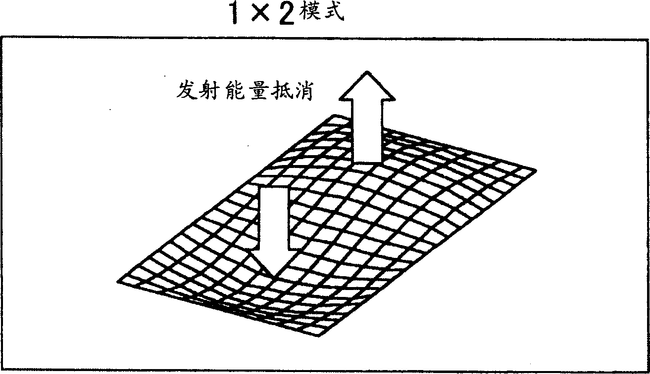
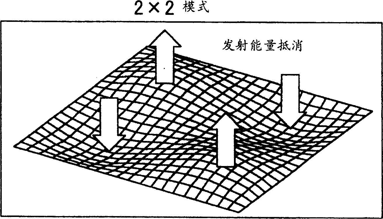
[0011] In addition, even if the 2×1 mode vibration is generated in a vibration region that is not a 2×1 rectangular shape, since the amplitude and distribution of the two vibration antinodes in the 2×1 mode are different, the respective vibrations of the two vibration antinodes There is a difference between the vibration volumes and there is a problem that the mutual canceling effect of the sound waves of each vibration antinode becomes weak

Method used


Image

  • Automotive floor panel structure
  • Automotive floor panel structure
  • Automotive floor panel structure

Examples


Embodiment Construction

[0061] Embodiments of the present invention will be described below with reference to the drawings.

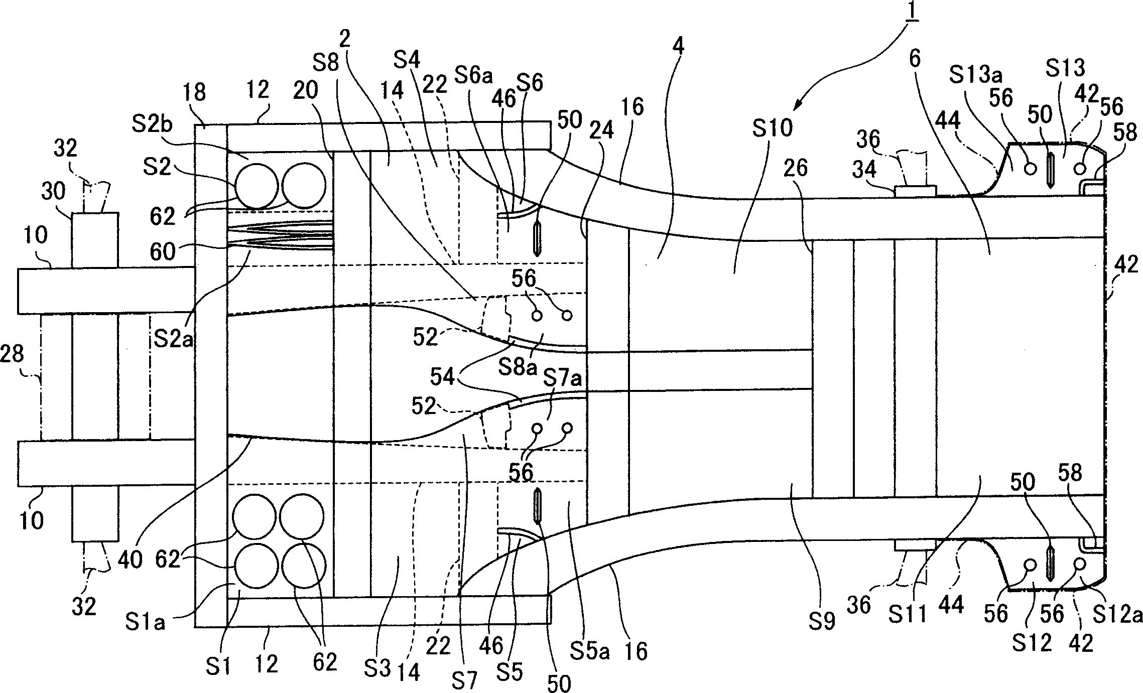
[0062] figure 1 is a plan view of an automobile body base provided with a body floor panel structure in an embodiment of the present invention.

[0063] Such as figure 1 As shown, the underbody 1 comprises a plurality of frame elements, and the front floor panel 2 constituting the floor portion of the vehicle compartment connected to the frame elements is located higher than the front floor panel 2 and behind the front floor panel 2 (in the direction of the vehicle body). ) at the position of the center floor panel 4, and the rear floor panel 6 constituting the trunk floor part, the rear floor panel 6 is located higher than the center floor panel 4 and behind the center floor panel 4 (in the direction of the vehicle body ) position.

[0064] Above-mentioned frame elements are front side frame 10, side sill 12, bottom side frame 14, rear side frame 16, No. 1 beam 18, No. 2 b...


PUM


Abstract

The present invention discloses a floor panel structure of a vehicle body, wherein the automobile floor includes a floor panel connected to a frame element of a vehicle body and also has a vibration mode adjustment structure capable of producing a 2×1 vibration mode within a predetermined frequency band. mode vibration to suppress the generation of acoustic emission. The floor panel has a non-rectangular vibration area, and the vibration mode adjustment structure of the floor panel has a vibration adjustment member defining a position of a node of 2×1 mode vibration, and the vibration adjustment member is disposed in the above-mentioned non-rectangular vibration area , so as not to be in contact with the frame member, and to form two areas where the vibration amounts of the two antinodes vibrating in the 2×1 mode are almost the same.

Description

technical field [0001] The present invention relates to a floor panel structure of a vehicle body, in particular to a floor panel structure of a vehicle body, wherein the floor includes a floor panel connected with a frame element of the vehicle body. Background technique [0002] It is well known that vibrations are transmitted from the frame connected to the engine or suspension to the floor panels, causing the floor panels to vibrate, with the result that the air in the passenger compartment vibrates violently, creating unpleasant vibrations and noises in the cabin. [0003] At this time, the vibration source that causes the above problems may be the vibration of the engine itself or the road noise transmitted from the suspension, and this road noise usually includes the component produced by the resonance in the tire and the component produced by the suspension resonance. [0004] Common means adopted to suppress such vibration and noise include the use of vibration-abso...

Claims


Application Information

Patent Timeline
Patent Type & Authority Applications(China)
IPC IPC(8): B62D25/20B62D21/10
CPCB62D21/10
Inventor 加村孝信知北胜
Owner MAZDA MOTOR CORP
Learn More