Method for separating semiconductor devices using nanoporous structure

A technology of acoustic vibration and facilities, applied in the direction of sound-generating equipment, mechanical equipment, engine functions, etc., can solve the problems of interference and overtaking in residential areas, and achieve the effect of low technology consumption

Inactive Publication Date: 2014-10-08
SIEMENS AG
View PDF5 Cites 0 Cited by
  • Summary
  • Abstract
  • Description
  • Claims
  • Application Information

AI Technical Summary

Problems solved by technology

As a result, not only adjacent residential areas are disturbed, but in the worst case permissible limit values ​​are exceeded, which conflicts with the operating permit given to the power plant

Method used


Image

  • Method for separating semiconductor devices using nanoporous structure
  • Method for separating semiconductor devices using nanoporous structure
  • Method for separating semiconductor devices using nanoporous structure

Examples


Embodiment Construction

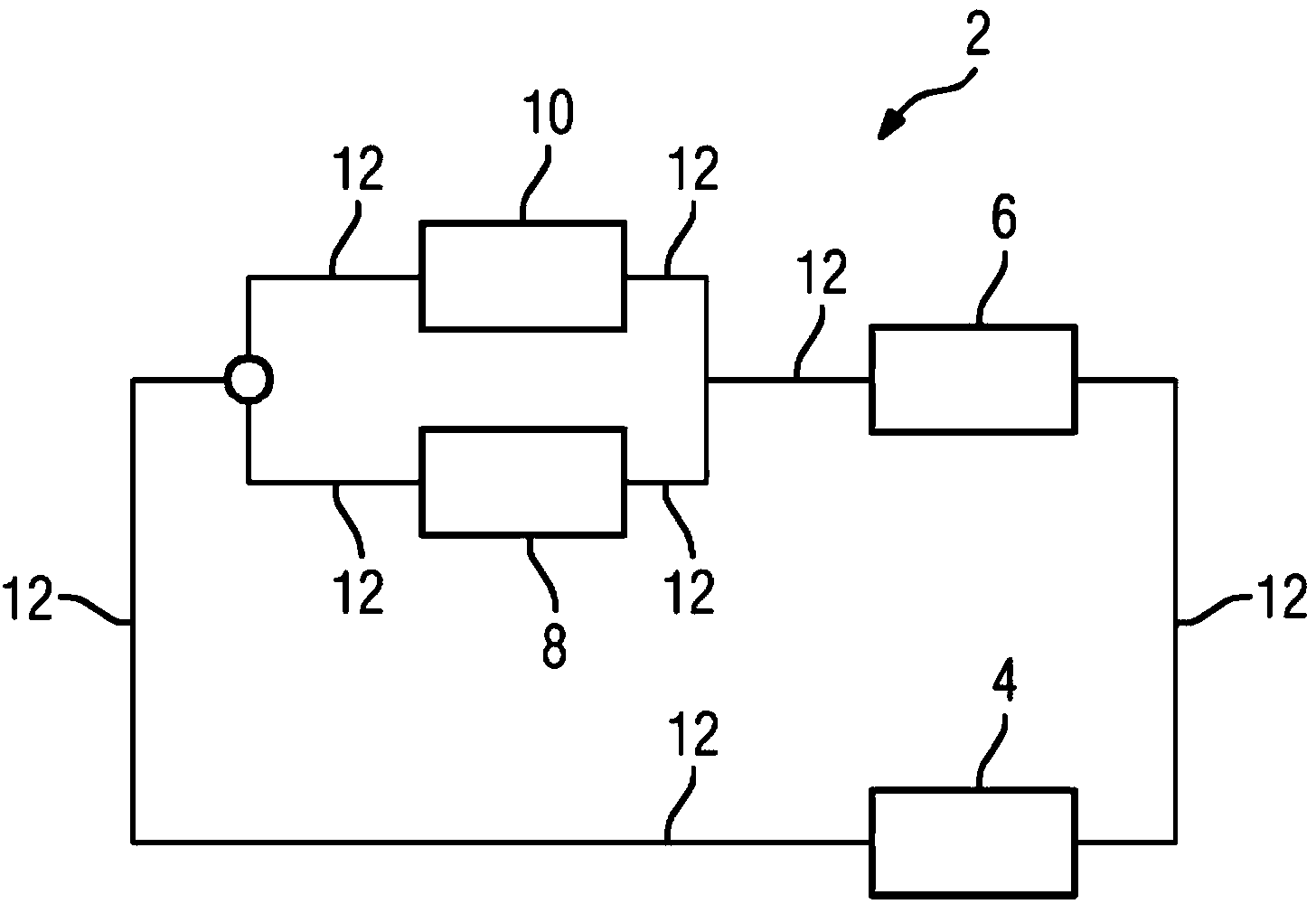
[0022] In the embodiment described hereinafter, the facility 2 is part of a power plant for the production of electrical energy and comprises therefor a steam generator 4, a condenser 6, a steam turbine 8, a bypass station 10 and a piping system substantially constructed of pipes 12. The piping system connects the individual components mentioned above to one another and serves to conduct the working medium, here water and steam.

[0023] as in figure 1 As shown in , two possible paths through the piping system 12 are provided for water or steam, wherein in load operation the water steam is guided through the steam turbine 8 and in no-load operation the water steam is guided through Bypass station 10.

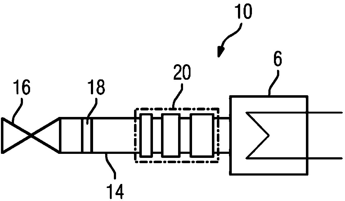
[0024] A very purposeful design variant of the bypass station 10 is in the figure 2 are shown according to the type of block diagram. The bypass station 10 is formed by a line 14 which is connected to the pipeline system 12 via a controllable bypass valve 16 . By correspond...


PUM


Abstract

The invention relates to a facility (2), in particular a power plant (2), comprising a steam turbine (8) and a bypass station (10) for diverting a working medium, as required, for the steam turbine (8) around the steam turbine (8), wherein at least one resonance absorber (20) is provided for the bypass station (10).

Description

technical field [0001] The invention relates to a plant, in particular a power plant, comprising a steam turbine and a bypass station for guiding a working medium for the steam turbine bypassing the steam turbine as required. Furthermore, the invention relates to a method for damping acoustic vibrations in a corresponding installation. Background technique [0002] In power plants it is often necessary to take measures for reducing the sound emissions of the power plant in order not to exceed permissible limit values ​​for the sound emissions. [0003] If, for example, steam turbines are used in the respective power plant, a bypass station is usually also provided in order to conduct the working medium for the steam turbine bypassing the steam turbine as required. A bypass station of this type usually includes a line by means of which the working medium is directed into the condenser without passing through the steam turbine. In this case, the working medium under pressure...

Claims


Application Information

Patent Timeline
Patent Type & Authority Applications(China)
IPC IPC(8): F01K13/00F01K27/00G10K11/172
CPCG10K11/172F01K27/00F01D25/04F01K13/006F05D2260/963
Inventor 斯特凡·米努特彼得·贝伦布林克弗兰克·戴德维希霍尔格·热当尼茨迪尔克·哈克里德贝恩德·普拉德霍斯特·乌韦·劳斯特凡·舍斯塔格
Owner SIEMENS AG
Why Eureka
Try Eureka