Sucting tube of refrigerator

A suction pipe, refrigerator technology, applied in the direction of fluid circulation arrangement, refrigeration components, refrigerators, etc., can solve the problems of weak shock resistance and vibration resistance, easy cracks in the annular pipe 22, etc., and achieve the effect of preventing cracks.

Inactive Publication Date: 2005-02-23
LG ELECTRONICS (TIANJIN) APPLIANCES CO LTD
View PDF0 Cites 2 Cited by
  • Summary
  • Abstract
  • Description
  • Claims
  • Application Information

AI Technical Summary

Problems solved by technology

Since the annular pipe 22 is formed by bending the entire suction pipe 20 into a circle, coupled with the characteristics of the copper pipe itself, work hardening will be caused at these processed parts, so that the shock and vibration resista

Method used


Image

  • Sucting tube of refrigerator
  • Sucting tube of refrigerator
  • Sucting tube of refrigerator

Examples


Example Embodiment

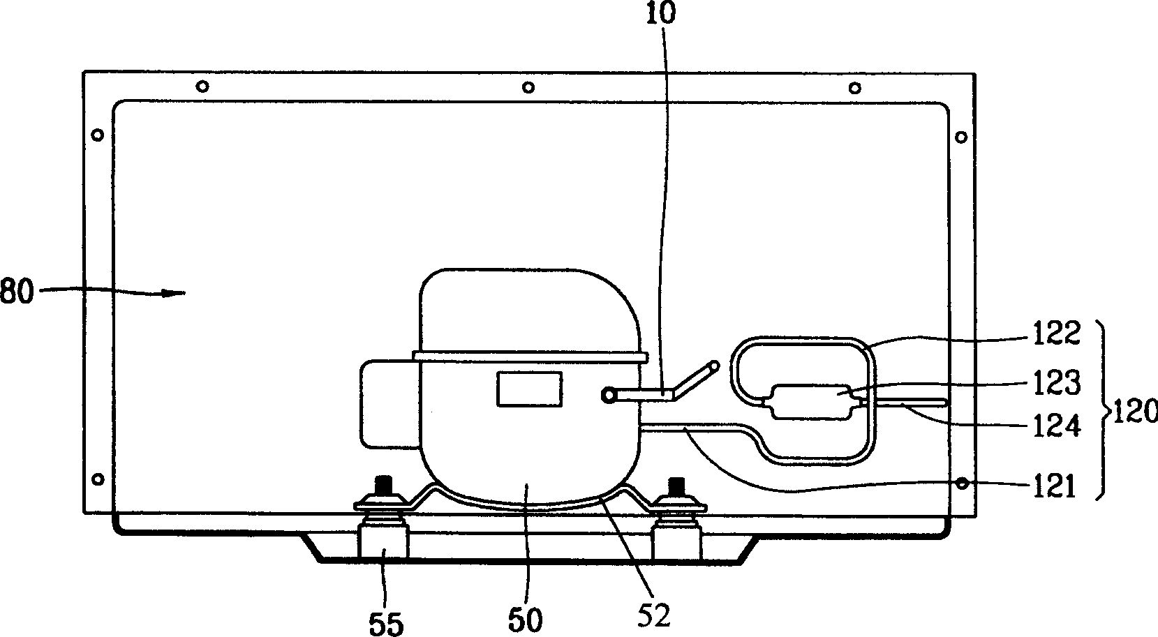
[0012] Such as image 3 As shown, the compressor 50 provided in the lower machine compartment 80 of the refrigerator provided by the present invention is fixedly connected to the bottom surface of the machine compartment 80 and the side surface of the compressor 50 by using a fixed base 52 and a shock-absorbing rubber 55 on the lower side thereof. The output pipe 10 and the suction pipe 120 are connected. Such as Figure 4 As shown, the suction pipe 120 includes: a compressor coupling pipe 121 connected to the compressor 50; an annular pipe 122 that can buffer the vibration transmitted by the compressor 50; and is connected to the ring in order to reduce the noise generated on the suction pipe 120 The silencer 123 on the shaped pipe 122; and the evaporator connection pipe 124 connected to the silencer 123 at one end and connected to the evaporator not shown in the figure at the other end. The annular tube 122 has a polygonal structure, which is composed of a plurality of work harde...


PUM


Abstract

An intake tube for refrigerator consists of a compressor-connecting pipe, a annular pipe, a silencer, and distiller-connecting pipe. The annular pipe is shaped in polyhedron. It makes multiple strengthened portions and linear stressed portions respectively, so that it can prevent intake tube from breaking as vibrations or impacts occur.

Description

technical field [0001] The invention relates to a refrigerator suction pipe, in particular to a refrigerator suction pipe with a ring structure. Background technique [0002] Usually, the mechanical room of the refrigerator is equipped with a compressor, a condenser, and a blower fan. Driven by the compressor, the gaseous refrigerant in a high-temperature and high-pressure state flows through various pipes in the refrigeration cycle system, and then passes through The evaporator condenses and returns to the compressor again. figure 1 It is a structural schematic diagram of the compressor installed in the mechanical room of the refrigerator and a part of the piping connected with the compressor in the prior art. figure 2 for figure 1 Schematic diagram of the suction pipe structure in . Such as figure 1 As shown, the compressor 50 arranged in the machine room 80 on the lower side of the refrigerator is fixedly combined with the bottom surface of the machine room 80 by mea...

Claims


Application Information

Patent Timeline
IPC IPC(8): F25B41/00
Inventor 方善旭
Owner LG ELECTRONICS (TIANJIN) APPLIANCES CO LTD
Why Eureka
Try Eureka