Coil device

A coil device and coil technology, applied in the field of coil devices and ferrite cores, can solve problems such as no mention of resin materials, no public solutions, etc., to achieve the effects of preventing cracks, satisfying miniaturization, and avoiding stress concentration

Active Publication Date: 2006-12-06
TDK CORPARATION
View PDF3 Cites 2 Cited by
  • Summary
  • Abstract
  • Description
  • Claims
  • Application Information

AI Technical Summary

Problems solved by technology

However, this prior art does not disclose a solution to the above-mentioned problems
[0020] Next, Patent Document 3 discloses a structure covered entirely by a casing

Method used


Image

  • Coil device
  • Coil device
  • Coil device

Examples


Embodiment Construction

[0127] Next, first to fifth aspects of the present invention will be described with reference to the drawings.

[0128] 1st form of this invention

[0129] Next, a first embodiment of the present invention will be described with reference to the drawings. In addition, in the drawings, the same symbols indicate the same or corresponding parts.

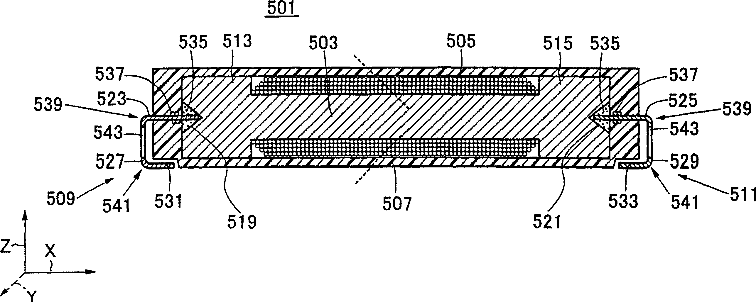
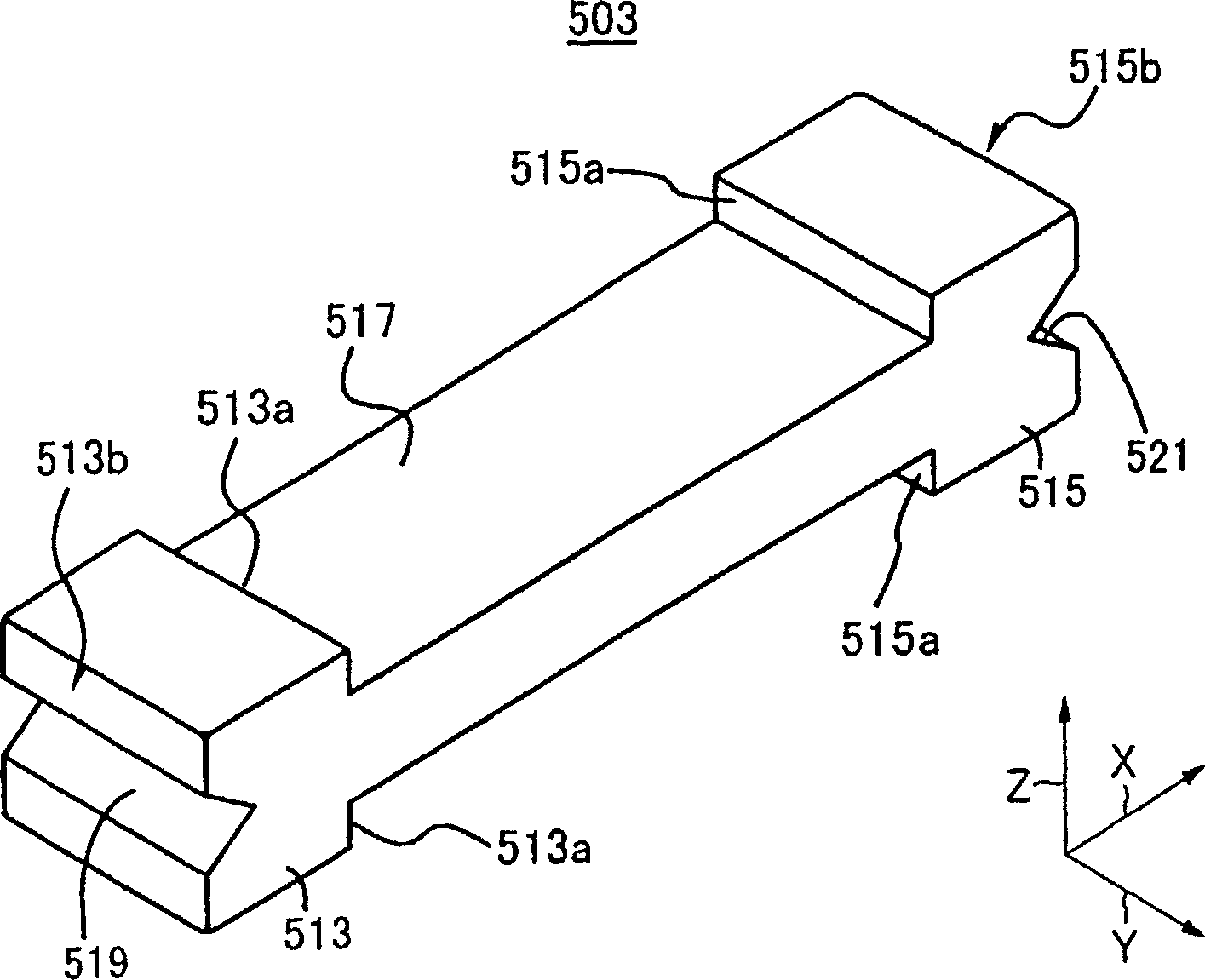
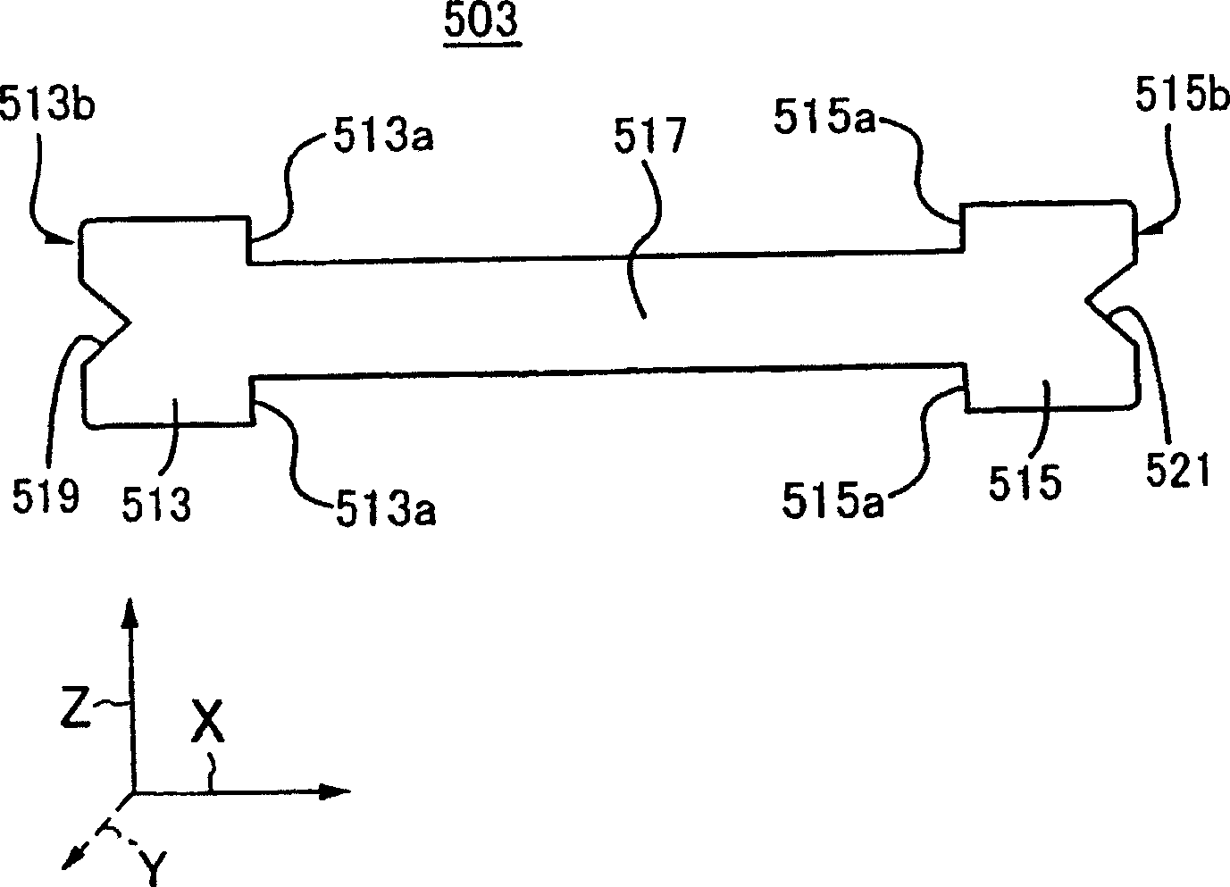
[0130] figure 1 The longitudinal section of the coil device of this embodiment is shown. The coil device 501 mainly includes: a ferrite core 503 , a coil 505 , an insulating outer casing 507 and a pair of terminals 509 and 511 . In addition, the coil device 501 is applicable to, for example, a two-way keyless entry system in an automobile that does not require button operation, an immobilizer, a tire pressure monitoring system, and the like.

[0131] The coil 505 is composed of a wire wound around the ferrite core 503 on the outer peripheral surface of the ferrite core 503 . An insulating outer case 507 is provided to cover the ent...


PUM


Abstract

A coil device in a part-winding form and a method for manufacturing a coil device are disclosed. The size of the core is small, and the windings do not collapse even though the form is simple. The coil device (501) comprises a ferrite core (503) and a coil (505) provided around the core. The coil (505) has at least a first coil portion (551) and a second coil portion (553). The boundary end surface (CF1), on the second coil side, of the first coil is so inclined that the inner circumferential side is nearer the second coil portion than the outer circumferential side. The boundary end surface (CF2), on the first coil side, of the second coil portion is so inclined that the outer circumferential side is nearer the first coil portion than the inner circumferential side.

Description

technical field [0001] The invention relates to a ferrite core and a coil device using the ferrite core. [0002] The coil device according to the present invention includes antennas suitable for vehicle-mounted transponders, etc., or inductors or choke coils for communication equipment. Background technique [0003] Conventionally, various types of coil devices have been proposed and put into practical use. As one of them, recently, a coil device applicable as an on-vehicle antenna or a transponder has been proposed. Coil devices suitable for such applications are required not only to be miniaturized but also to maintain stable inductance in the frequency band desired by customers. For this reason, a divided winding form in which a coil portion wound in layers in the radial direction is divided with respect to the axial direction of the magnetic core is also devised. [0004] That is, in the divided winding form described in Patent Document 1, a flange integrally formed ...

Claims


Application Information

Patent Timeline
IPC IPC(8): H01F27/02
Inventor 山下充弘长坂孝三浦英树松川泰弘佐藤和男佐藤玲佐藤广宣伊东孝之北岛保彦
Owner TDK CORPARATION
Why Eureka
Try Eureka