Novel chilling block for casting

A cold iron, a new type of technology, applied in the field of casting, can solve the problems of casting scrap, increase casting welding repair rate, looseness, etc., to achieve the effect of improving heat conduction, improving chilling effect, and increasing heat dissipation area

Inactive Publication Date: 2021-05-04
SHANGHAI HULIN HEAVY IND
View PDF5 Cites 2 Cited by
  • Summary
  • Abstract
  • Description
  • Claims
  • Application Information

AI Technical Summary

Problems solved by technology

However, in the process of use, cracks occasionally appear at the junction of the edge of the cold iron; or after processing, due to the weak chilling effect of the cold iron, defects such as subcutaneous shrinka

Method used


Image

  • Novel chilling block for casting
  • Novel chilling block for casting
  • Novel chilling block for casting

Examples


Example Embodiment

[0027] Example 1

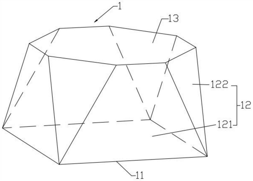
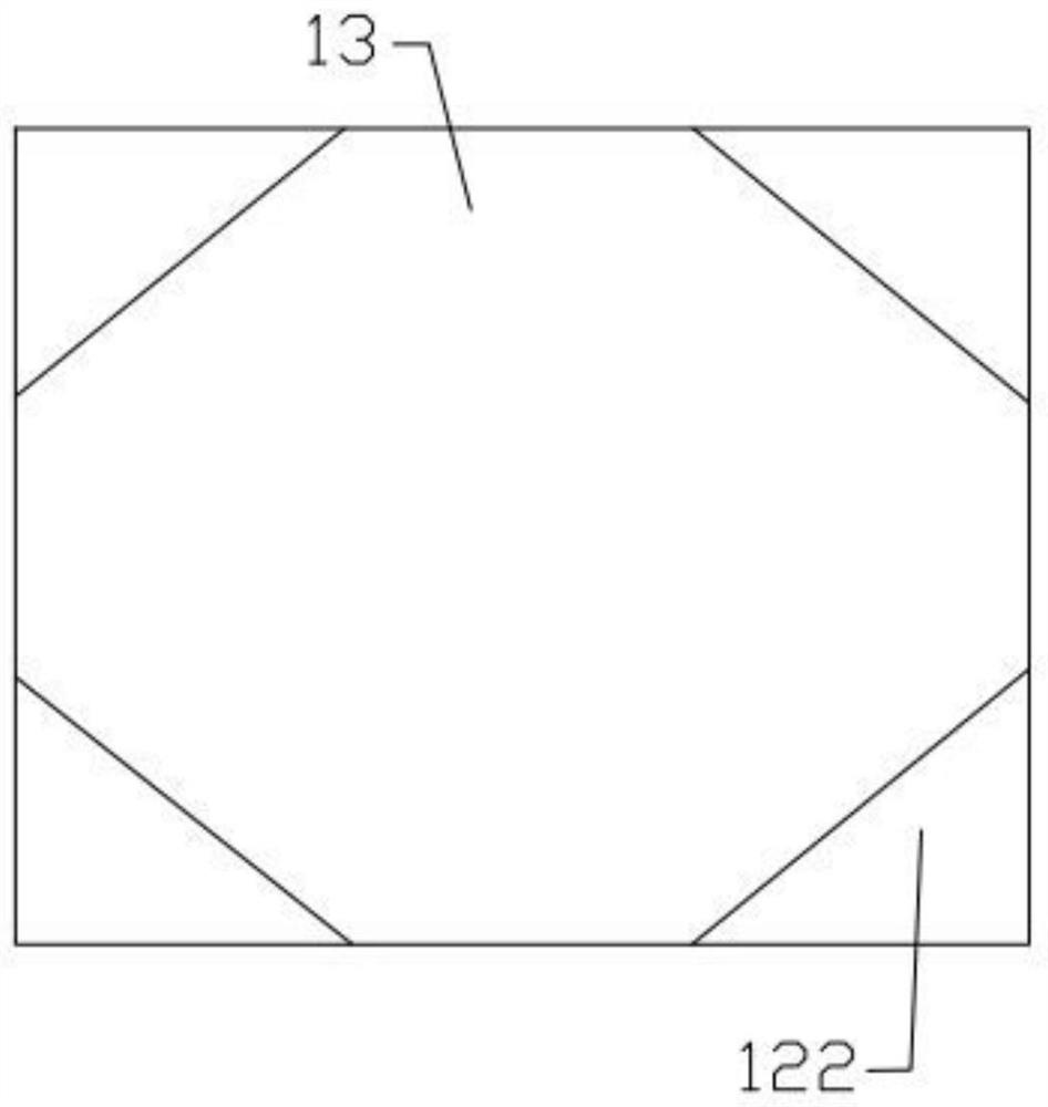
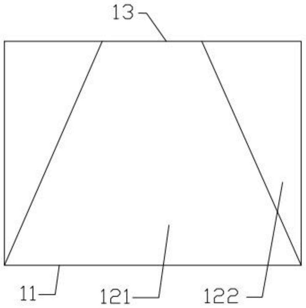
[0028] A new type of cold iron for casting, see Figure 1 to Figure 4 , the cold iron 1 has a bottom surface 11, a top surface 13 and a side surface 12, the bottom surface 11 is used to contact the surface of the casting 2, the bottom surface 11 and the top surface 13 are connected by the side surface 12, and the cross-sectional area of ​​the cold iron 1 is from the bottom surface 11 to the top The face 13 is gradually reduced. The thickness of the cold iron 1 gradually decreases from the center to the edge. The side surface 12 includes a first side surface 121 in the shape of a trapezoid and a second side surface 122 in the shape of a triangle. The first side surface 121 and the second side surface 122 are arranged at intervals connected end to end. The top side of the triangle and the bottom side of the triangle form the side of the top surface 13 , and the bottom side of each trapezoid forms the side of the bottom surface 11 .

[0029] In this embodime...

Example Embodiment

[0039] Example 2

[0040] see Figure 5 , in this embodiment, the bottom surface 11 is a triangle, the top surface 13 is a hexagon, and other features can be the same as or similar to those in Embodiment 1, such as a first side 121 and a second side 122, and the first side is trapezoidal. , the second side is triangular. However, in this embodiment, the number of surfaces of the first side surface 121 is three, and the number of surfaces of the second side surface is three, which can also achieve the effect of uniform transition of the chilling effect.

Example Embodiment

[0041] Example 3

[0042] see Image 6 , in this embodiment, the bottom surface 11 is a pentagon, the top surface 13 is a decagon, and other features can be the same as or similar to those in Embodiment 1, such as a first side 121 and a second side 122, the first side It is trapezoidal and the second side is triangular. However, in this embodiment, the number of surfaces of the first side surface 121 is five, and the number of surfaces of the second side surface is five, which can also achieve the effect of uniform transition of the chilling effect.


PUM


Abstract

The invention discloses a novel chilling block for casting. The chilling block is provided with a bottom surface, a top surface and side surfaces, wherein the bottom surface is used for being in contact (including direct contact and indirect contact) with the surface of a casting, the bottom surface and the top surface are connected (including direct connection and indirect connection) through the side surfaces, and the cross section area of the chilling block is gradually reduced from the bottom surface to the top surface. The novel chilling block is simple and ingenious in structure and easy to machine, the corresponding technical effect can be effectively achieved, the chilling effect at the edge junction is gently transited, and the situation that the casting cracks at the edge of the chilling block is effectively avoided. Besides, due to a polygon structure, the heat dissipation area is enlarged, the conduction of heat energy is improved, the chilling effect of the chilling block is improved, the product quality of the casting is ensured, and the quality of the casting is improved.

Description

technical field [0001] The invention relates to a novel cold iron for casting, which belongs to the technical field of casting. Background technique [0002] In the casting production process, due to the different complexity of the casting parts and the uneven wall thickness, the cooling rate of each part during the solidification process is inconsistent, and casting defects are easily generated. In order to ensure the quality of castings, chill iron is usually placed inside or on the surface of the cavity to be chilled to control shrinkage and obtain directional solidification to improve feeder feeding efficiency and prevent casting defects such as shrinkage cavities and porosity. [0003] At present, cold iron is usually cast from carbon steel or cut from steel plate. In terms of size, except for the conformal cold iron, the square regular cold iron is basically used and placed on the working surface to be chilled. However, in the process of use, cracks occasionally appe...

Claims


Application Information

Patent Timeline
IPC IPC(8): B22D15/04
CPCB22D15/04
Inventor 金志宏朱峰刘为国余全蔡常林许久海
Owner SHANGHAI HULIN HEAVY IND
Why Eureka
Try Eureka