Optical engine lighting system

A lighting system and optical engine technology, applied in optics, optical components, nonlinear optics, etc., can solve problems such as low product qualification rate, color cast of projection screen, complicated process technology, etc., and achieve simple structure and technical difficulty and low cost , cost reduction effect

Inactive Publication Date: 2005-03-02
XINCHENG ZHIDIAN NETWORK TECH CO LTD SHANGHAI
View PDF1 Cites 1 Cited by
  • Summary
  • Abstract
  • Description
  • Claims
  • Application Information

AI Technical Summary

Problems solved by technology

The fly-eye lens array, PCS array light source and dichroic mirror beam-splitting system used in traditional projection display devices have problems such as complex process technology, low product qualification rate and high cost, and the projection screen using dichroic mirror beam-splitting system has problems Defects such as color cast

Method used


Image

  • Optical engine lighting system
  • Optical engine lighting system
  • Optical engine lighting system

Examples


Embodiment Construction

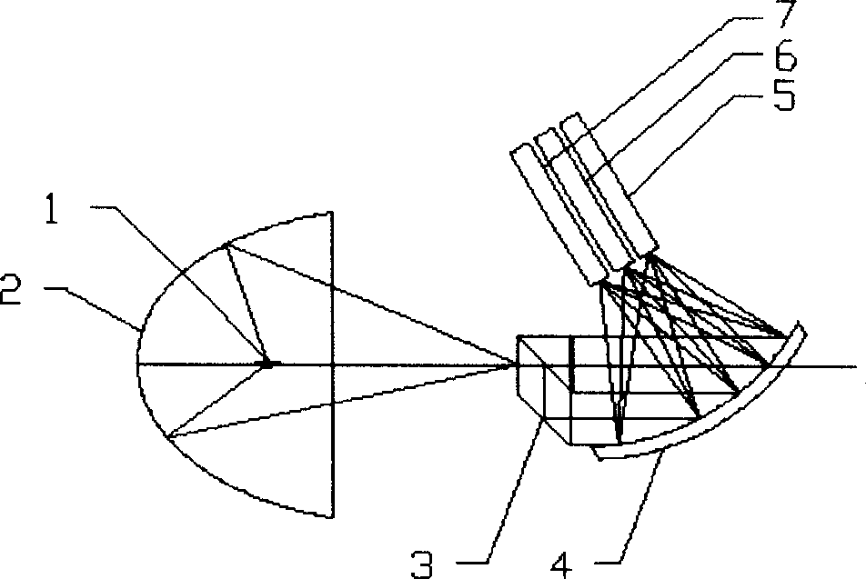
[0017] Such as figure 1 As shown, the present invention includes: a white light source 1, an ellipsoidal reflective bowl 2, a non-array polarizing prism group 3, a grating device 4, and optical rod devices 5, 6, and 7. The white light source 1 is placed at one focal point of the ellipsoidal reflective bowl 2, and its white light beam converges at the other focal point of the ellipsoidal reflective bowl to form the incident light spot of the system. The incident light spot is incident on the non-array polarizing prism group 3, and the beam-splitting surface of the non-array polarizing prism group 3 decomposes the incident light into the transmitted P component and the reflected S component, wherein the S component is reflected by the prism again and exits along the optical axis direction, while The P component is converted to the S component after being passed through a half-wave plate. If the half-wave plate is moved below the prism, the system will output P-polarized light. ...


PUM


Abstract

The invention is an optical engine illuminating system applied to projecting technology field, the lamp house is arranged on the focus of elliptical reflecting bowl, the beam is gathered on another focus of the reflecting bowl, forms the incidence white light spot of the system; or the illuminating lamp house is arranged on the focus of the reflecting bowl with parabola type, its beam is emitted out nearly parallel after being reflected by the reflecting bowl, the white light spot enters the back non-array polarization prism group, the polarization state of the output beam is controlled by the polarization prism group, the polarization light converted by the non-array polarization prism group enters the grating device on the direction of the non-array polarization prism group, the white light is divided into spectrum light through the grating, then uses the light bar device to collect the spectrum light. The invention is simple and the cost is low.

Description

technical field [0001] The invention relates to an optical engine lighting system, in particular to an optical engine lighting system containing a grating and a light bar device, which is used in the projection technology field. Background technique [0002] The lighting system is an important part of the optical engine of the projection display device, and has a great influence on the cost and main performance indicators of the projection display device. The optical engine has very high requirements on the light illumination system, mainly including: the illuminance in the whole field of view should be very uniform, the light energy utilization rate should be as large as possible, the illumination light field is linearly polarized light with a very high degree of polarization, and the color spectrum of the illumination light The range is wide and the intensity is balanced, and the vibration direction of the linearly polarized light of each chromatographic channel can be adj...

Claims


Application Information

Patent Timeline
Patent Type & Authority Applications(China)
IPC IPC(8): G02B27/18G02F1/13G03B21/14H04N5/74H04N9/31
Inventor 邓运明田贺斌
Owner XINCHENG ZHIDIAN NETWORK TECH CO LTD SHANGHAI
Why Eureka
Try Eureka