File appliance

A technology of folders and folders, applied in the field of folders, can solve the problem that the stapler cannot be burned, and achieve the effect of a stable bonding state

Inactive Publication Date: 2005-03-09
KOKUYO CO LTD
View PDF1 Cites 1 Cited by
  • Summary
  • Abstract
  • Description
  • Claims
  • Application Information

AI Technical Summary

Problems solved by technology

[0005] Therefore, in the case of incinerating the folder 57 for disposal, the staple 58 of the stapler cannot be incinerated.

Method used


Image

  • File appliance
  • File appliance
  • File appliance

Examples


Embodiment Construction

[0036] Hereinafter, preferred embodiments of the present invention will be described with reference to the accompanying drawings.

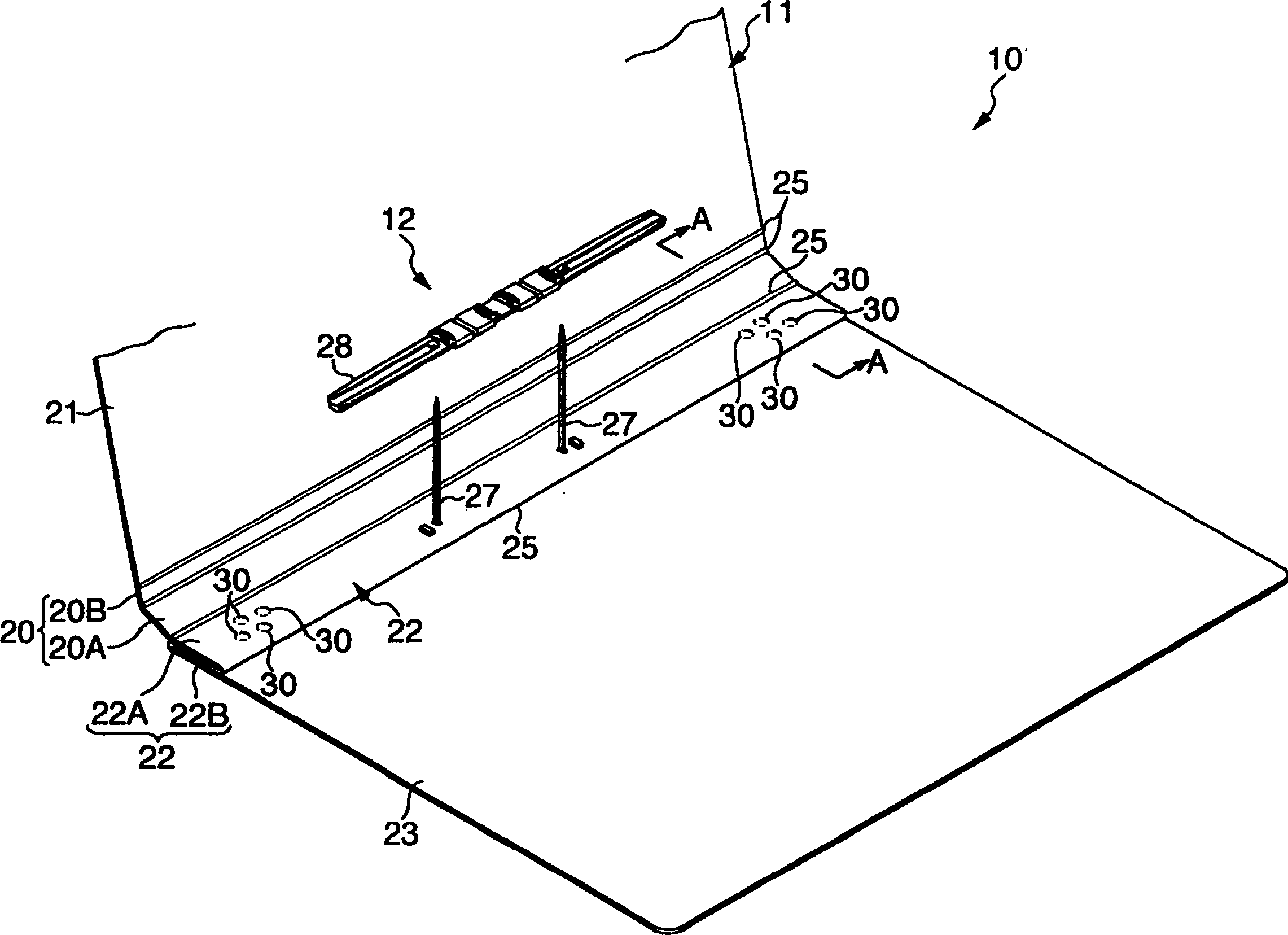
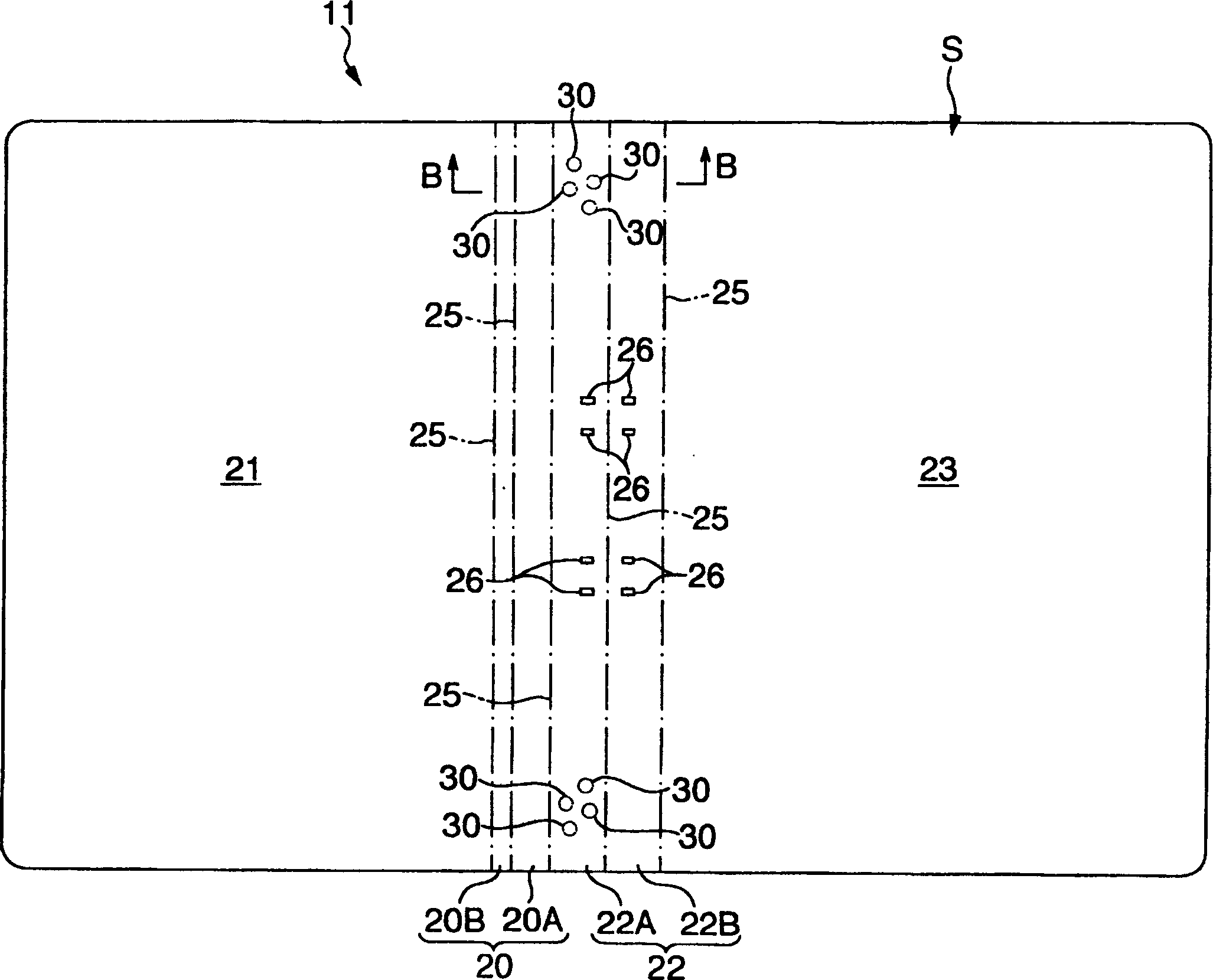
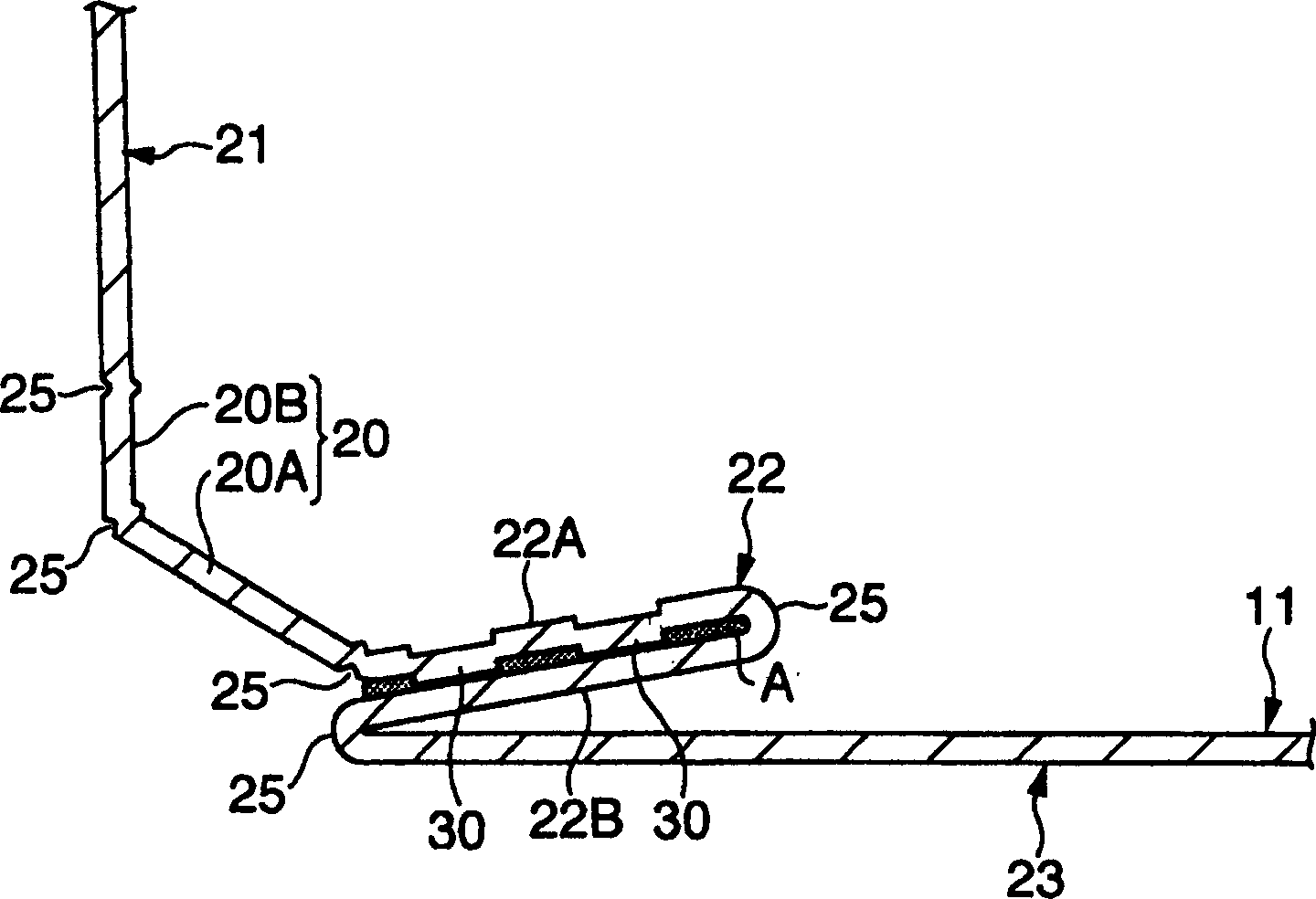
[0037] exist figure 1 In , a schematic perspective view of the file folder of this embodiment is shown, and in figure 2 , an expanded view of the jacket body is shown. In these figures, the file 10 is constituted by a jacket body 11 and a binder 12 detachably provided on the jacket body 11 .

[0038] The jacket body 11 is formed by, for example, figure 2 The shown is composed of a thin plate S with a thickness of about 0.5 mm, which is composed of a piece of hard paper. The jacket body 11, in the state of the material before formation, that is, in the state of the thin plate S, is generally rectangular in plan view, and is designed to have a clip back 20 at a substantially central portion in the longitudinal direction, and a clip is connected to the left side of the clip back 20. On the other hand, on the right side, the surface 21 is conne...


PUM


Abstract

The folding part 22 for installing a binding member 12 is provided to an inner surface side of a cover body 11. The folding part is composed of a pair of folding part forming pieces 22A, 22B wherein a part of paper-made sheet S is superimposed in two sheets thickness, and a protrusion 30 formed by press impression is formed inside a surface of the folding part forming piece 22A of one side. When the folding parts are bonded to each other by applying water soluble adhesive A to joint surfaces of the folding part made piece, an adhesion state is stably maintained by the protrusion 30.

Description

[0001] technical area [0002] The present invention relates to file folders, and particularly relates to file files that are recyclable without contamination. Background technique [0003] like Figure 5 As shown, there is known a file (strip file) 57 in which a part of the sheet S constituting the jacket body 50 is overlapped in two layers on the inner surface side of the jacket body 50 to form a folded portion 52 . A binder 56 including a binding leg 53 and a binding plate member 54 is detachably provided in the region of the folded portion 52 . [0004] However, in such a file file 57, a pair of folded-in portion forming pieces 52A formed by overlapping with each other so as to form the folded-in portion 52 are inserted into the surfaces of the staples 58 of the stapler to maintain the thickness of two layers. Structure. [0005] Therefore, when the folder 57 is burnt for disposal, the staples 58 of the stapler cannot be burnt, and when reproduction is desired, a trouble...

Claims


Application Information

Patent Timeline
IPC IPC(8): B42F7/00B42D3/04B42F13/06
Inventor 小池诚一
Owner KOKUYO CO LTD
Why Eureka
Try Eureka