Ice making machine hoving fan component element

A fan assembly and ice maker technology, applied in ice making, ice making, household appliances, etc., can solve problems such as unsmooth flow of cold air, complex design of ice machine, large loss of cold air flow, etc., to achieve no flow loss and high efficiency Improvement and smoothness provided by the effect

Inactive Publication Date: 2005-03-09
LG ELECTRONICS (TIANJIN) APPLIANCES CO LTD
View PDF0 Cites 7 Cited by
  • Summary
  • Abstract
  • Description
  • Claims
  • Application Information

AI Technical Summary

Problems solved by technology

This structure makes the overall weight center of the ice maker on one side of the fan assembly 10, so the design of the ice maker becomes complicated
[0012] In addition, the opening directions of the suction port 18 and the discharge port 20 in the fan assembly 10 of the prior art are not in a straight line, and the flow of cold air is relatively unsmooth.
That is, there is a problem that the cooling air flow loss in the fan assembly 10 is large.

Method used


Image

  • Ice making machine hoving fan component element
  • Ice making machine hoving fan component element
  • Ice making machine hoving fan component element

Examples


Embodiment Construction

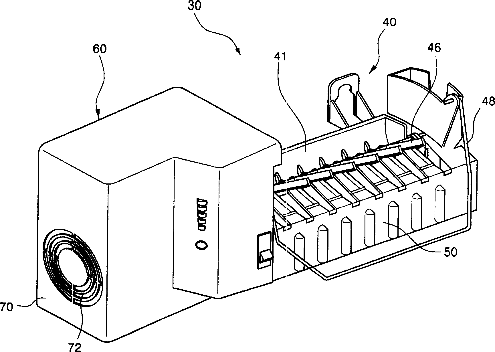
[0027] In order to achieve the above objective, the present invention provides an ice maker equipped with a fan assembly. The ice maker includes an ice maker body 40 composed of a body frame 41, mounted on the body frame 41 and providing cold air to the ice making tray 45. The fan assembly 60; where the fan assembly 60 includes: composed of the first and second frame portions 62a / 62b, the interior of which is divided by the dividing plate 64 and forms a cold air flow path 64f, which is connected to the cold air flow path 64f and made ice The plate 45 provides the frame 62 of the cold air exhaust pipe 66; the box fan 80 that is fixedly combined with the cold air flow path 64f inside the first and second frame portions 62a / 62b to provide the driving force of the cold air; The frame portions 62a / 62b are elastically suspended and assembled on the assembling hook 69 of the body frame 41.

[0028] The joint between the first and second frame portions 62a / 62b is a concave-convex joint 63...


PUM


Abstract

An ice maker with fan module is composed of a main body with frame, and a fan module for providing cold air to ice making tray. Said fan module consists of the first and the second frames, cold air channel, cold air outlet tube, box-type fan, and installing hooks for hanging said two frames on the frame of main body.

Description

Technical field [0001] The present invention relates to an invention related to an ice maker, and particularly to an invention of a fan assembly ice maker that provides cold air to the ice making tray to make ice more quickly. Background technique [0002] In home appliances such as refrigerators, there is an ice maker capable of making ice to provide users with ice. The low-temperature air inside the refrigerator, that is, cold air is supplied to the ice making tray, so that ice can be made quickly. The structure of the above ice maker is as figure 1 Shown. [0003] The ice maker body 1 has an ice making tray 3. Generally, the ice tray 3 is divided into a plurality of spaces. The symbol 5 in the figure is an ice detector. On one side of the ice maker body 1 is a driving part 7 that drives the ice tray 3 and the ice detection lever 5 with a motor and the like installed inside. [0004] The drive unit 7 is provided with a detachable fan assembly 10. The fan assembly 10 forcibly p...

Claims


Application Information

Patent Timeline
IPC IPC(8): F25C1/12
Inventor 金日新
Owner LG ELECTRONICS (TIANJIN) APPLIANCES CO LTD
Why Eureka
Try Eureka