A multiple-view directional display

A display, multi-view technology, applied in display devices, static indicators, instruments, etc., can solve problems such as small angle separation

Active Publication Date: 2005-03-09
UNIFIED INNOVATIVE TECH
View PDF8 Cites 43 Cited by
  • Summary
  • Abstract
  • Description
  • Claims
  • Application Information

AI Technical Summary

Problems solved by technology

[0026] A problem in many existing multi-view directional displays is that the angular separation between the two images is too small

Method used


Image

  • A multiple-view directional display
  • A multiple-view directional display
  • A multiple-view directional display

Examples


Embodiment Construction

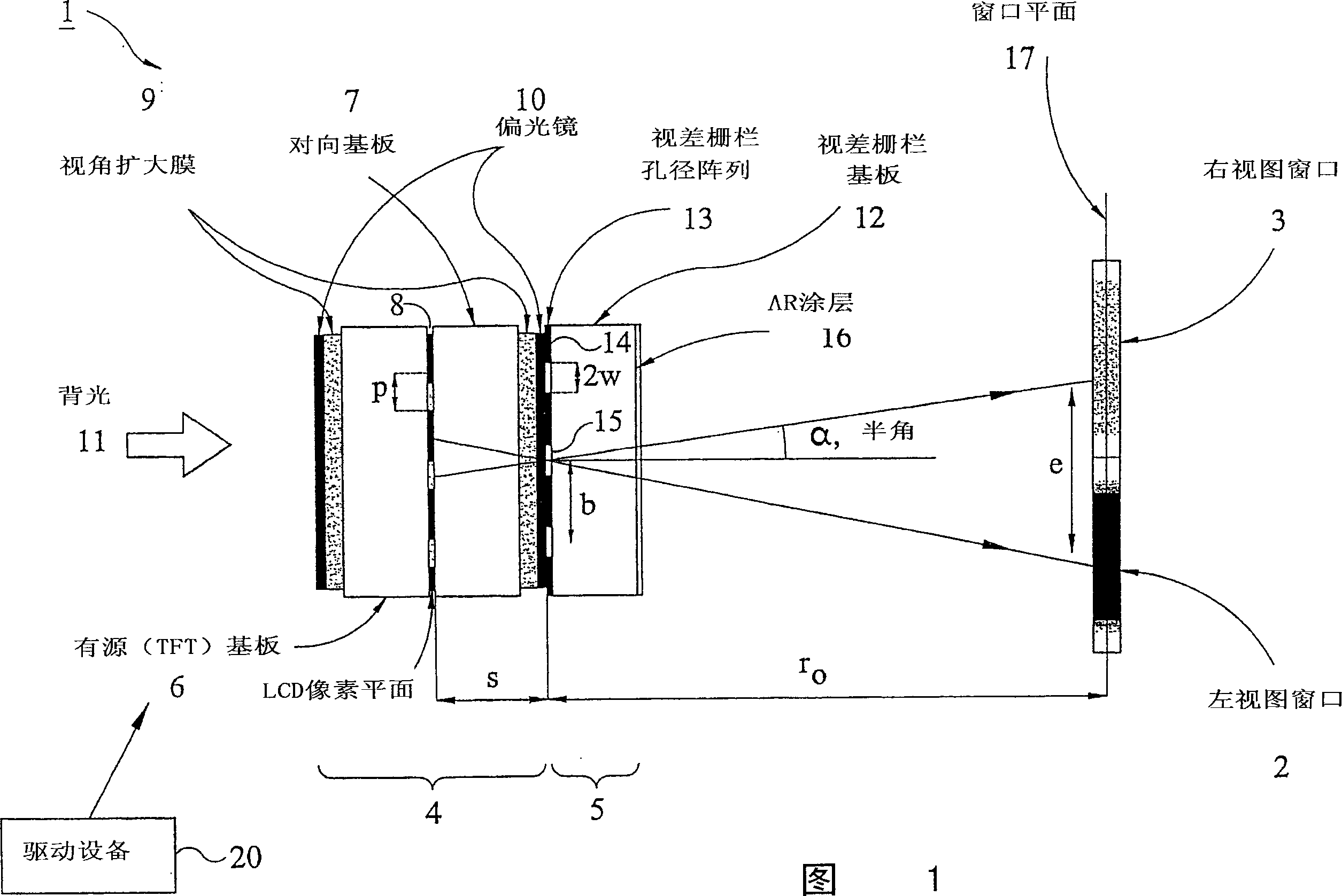
[0058] Figure 8 illustrates the installation of the display 40 in a relatively narrow car 41 and a relatively wide truck. This multi-view display is a dual-view type, and it is exemplified to include a liquid crystal display (LCD) 43 having alternating pixel columns of interlaced vertical bands displaying the left-side viewer image L and the right-side viewer image R. The distance between the parallax optical element in the form of a lenticular screen 44 and the pixel plane of the LCD 43 is the thickness of the LCD substrate and related layers, which is about 0.7 mm in this example. The display is of the front parallax optical element type, but in the case of all the embodiments described below, it may also be of the back parallax optical element type.

[0059] The optical system 45 is arranged in front of the lenticular screen 44 and includes a divergent lens in the form of a plano-concave lens, and the lens or small lenticular layer of the lenticular screen 44 is a plano-convex ...


PUM


Abstract

A multiple view display comprises a display device which displays first and second images in a spatially multiplexed fashion across the display surface. The device cooperates with a parallax optic such as a lenticular screen so as to act as a directional display sub-system directing light from the first and second images in different viewing directions. An optical system, for example comprising a lenticular screen of diverging elements, changes the angular separation of the viewing angle directions, for example so as to increase the angular separation.

Description

Technical field [0001] The invention relates to a multi-view directional display, which displays two or more images so that the visible direction of each image is different. Thus, two or more viewers viewing the display from different directions will see different images from each other. Such a display can be used for, for example, an autostereoscopic display or a dual-view display. Background technique [0002] For many years, traditional displays were designed to be viewed by multiple users at the same time. The display characteristics of the display are made so that the viewer can view the same high-quality image quality from different angles relative to the display. This is effective in applications where many users require the same information from the display, such as displaying departure information in airports and train stations. However, there are many applications where individual users want to be able to see different information from the same display. For example, in ...

Claims


Application Information

Patent Timeline
Patent Type & Authority Applications(China)
IPC IPC(8): G02F1/13G02B27/01G02B27/22G02F1/133G02F1/1335H04N13/00H04N13/04
CPCH04N13/0454H04N13/045H04N13/0404H04N13/0418G02F1/1323H04N13/0409H04N13/305H04N13/31H04N13/32H04N13/354H04N13/359
Inventor J·马瑟D·J·蒙特格玛瑞R·温劳G·布尔希尔N·M·巴瑞特
Owner UNIFIED INNOVATIVE TECH
Why Eureka
Try Eureka