Projecting lighting system and projecting lighting method thereof

A lighting system and projection technology, applied in the field of projection lighting systems, can solve the problems of reducing and wasting lighting efficiency, and achieve the effect of improving lighting efficiency

Inactive Publication Date: 2005-03-09
DELTA ELECTRONICS INC
View PDF0 Cites 9 Cited by
  • Summary
  • Abstract
  • Description
  • Claims
  • Application Information

AI Technical Summary

Problems solved by technology

Therefore, part of the projected beam cannot enter the light-receiving area of ​​the optical path switching device 102, which obviously causes waste of light and reduces the lighting efficiency.

Method used


Image

  • Projecting lighting system and projecting lighting method thereof
  • Projecting lighting system and projecting lighting method thereof
  • Projecting lighting system and projecting lighting method thereof

Examples


Embodiment Construction

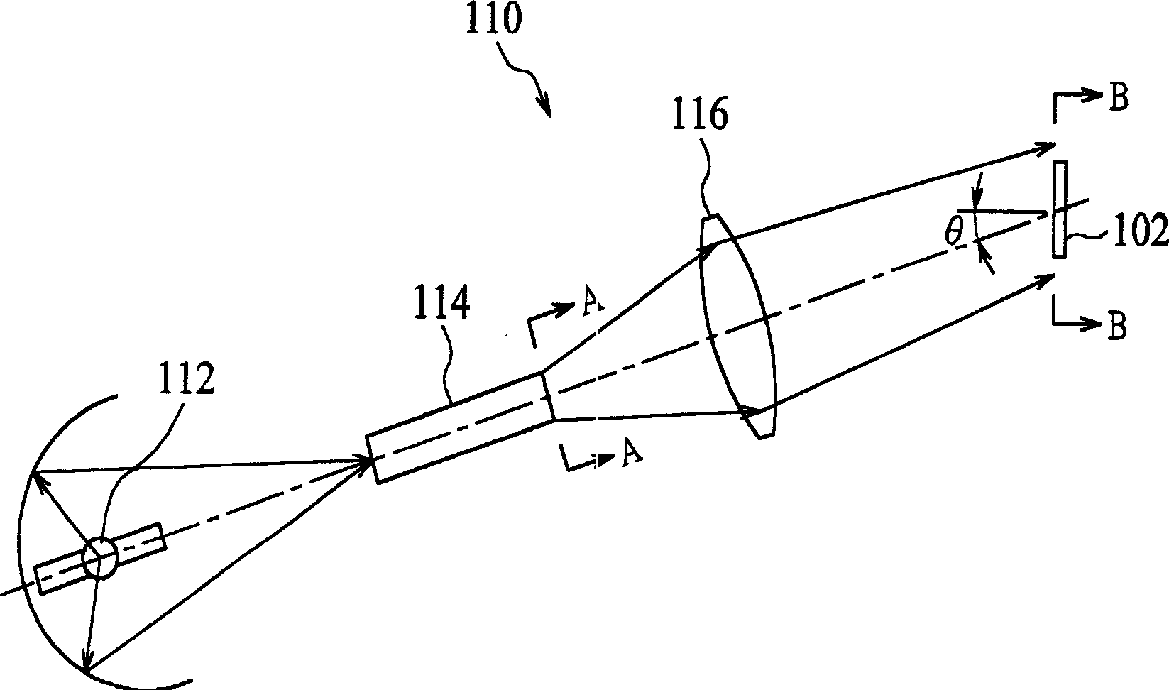
[0044] image 3 A schematic diagram of a projection lighting system 10 is shown according to an embodiment of the present invention. Such as image 3 As shown, the projection lighting system 10 includes a light source 12, a light guide 14, an optical path turning device 16, and an optical path switching device 20, and the optical path switching device 20 has at least one optical path switching element 20a.

[0045] The light source 12 is used for providing illumination light to the projection illumination system 10 . A light concentrator, such as an ellipsoid reflector 24 , can be arranged around the light source 12 to concentrate the light beam emitted by the light source 12 . The light path turning device 16 is used to transfer the light beam from the light guide 14 to the light path switching device 20 . The optical path turning device 16 is composed of, for example, an internal total reflection prism 26 for changing the projection direction and a transmission lens group...


PUM


Abstract

The present invention relates to projection lighting system. It includes a light-conducting pipe and an optical circuit switching device with light-receiving region, The light-conducting pipe is placed in the optical cirucit between light source and optical circuit switching device. The light beam emitted by means of end face of light-conducting pipe can be income into the light-receiving region in the mode of that said light beam and plane normal of light receiving region are formed into a certain angle, and its producted projection pattern form can produce a tension change relatively to light-conducting pipe end face form along said off-axis angle change direction, and the end form of ligh- conducting pipe is a parallegram whose inner angle along off-axis angle direction is larger than adjacent inner angle.

Description

technical field [0001] The invention provides a projection lighting system, in particular a projection lighting system which can effectively improve lighting efficiency. Background technique [0002] The principle of the existing optical projection display is to project the light beam emitted by the light source to an optical path switching device. The optical path switching device has a plurality of tiny optical path switching elements that can switch the optical path. These tiny optical path switching elements are combined into an image, and then passed through the projection system to project to the display screen. Take the Digital Micromirror Device (DMD) manufactured by Texas Instruments (TI) as an example. It is composed of multiple micromirrors. By selectively controlling the mirrors at two different inclination angles, the beam passes through The two states of the transmissive projection system (that is, the bright state mode) and the non-transparent projection syst...

Claims


Application Information

Patent Timeline
Patent Type & Authority Applications(China)
IPC IPC(8): G02B6/00G02F1/13G03B21/14
Inventor 张绍雄
Owner DELTA ELECTRONICS INC
Why Eureka
Try Eureka