
Submersible motor for hot water well

A submersible motor, hot water well technology, applied in electrical components, electromechanical devices, electric components and other directions, can solve the problems of mechanical seal failure, easy scaling, low temperature resistance, etc., to achieve reliable mechanical seal, avoid high temperature vaporization, manufacturing simple method effect

Active Publication Date: 2005-03-09
天津市百利溢通电泵有限公司
View PDF2 Cites 0 Cited by
  • Summary
  • Abstract
  • Description
  • Claims
  • Application Information

AI Technical Summary

Problems solved by technology

[0005] But aforementioned known technology all can not well solve following problem:
[0006] First of all, the mechanical seal problem, the mechanical seal is easily scaled (calcium carbonate, magnesium carbonate, calcium sulfate, magnesium sulfate) when exposed to high-temperature groundwater, and the water vaporization volume inside the motor expands too much to exceed the breathing capacity of the motor tail capsule. The seal creates a large back pressure, which will cause the mechanical seal to fail
After the mechanical seal fails, groundwater entering the motor will also cause fouling and damage the motor
[0007] In addition, there is the problem of high-temperature vaporization of water inside the motor. After water vaporizes at high temperature, the sliding bearings, especially the upper bearing of the motor, will be damaged due to dry grinding, and the high temperature generated by the dry grinding of the bearings will accelerate the vaporization of water and cause greater damage.
[0008] Also, there is the problem of the temperature resistance of the electromagnetic wire. Although the plastic insulated electromagnetic wire has good water resistance, the temperature resistance is low, and the maximum generally does not exceed 90°C (hot water temperature + motor temperature rise), which cannot meet the environmental requirements of higher water temperature conditions.

Method used


Image

  • Submersible motor for hot water well
  • Submersible motor for hot water well
  • Submersible motor for hot water well

Examples


Embodiment Construction

[0029] Below in conjunction with preferred embodiments, the specific implementation, features and effects provided by the present invention are described in detail as follows; for the purpose of simplicity and clarity, the description of known technologies is appropriately omitted below to avoid unnecessary details Affect the description of this technical solution.

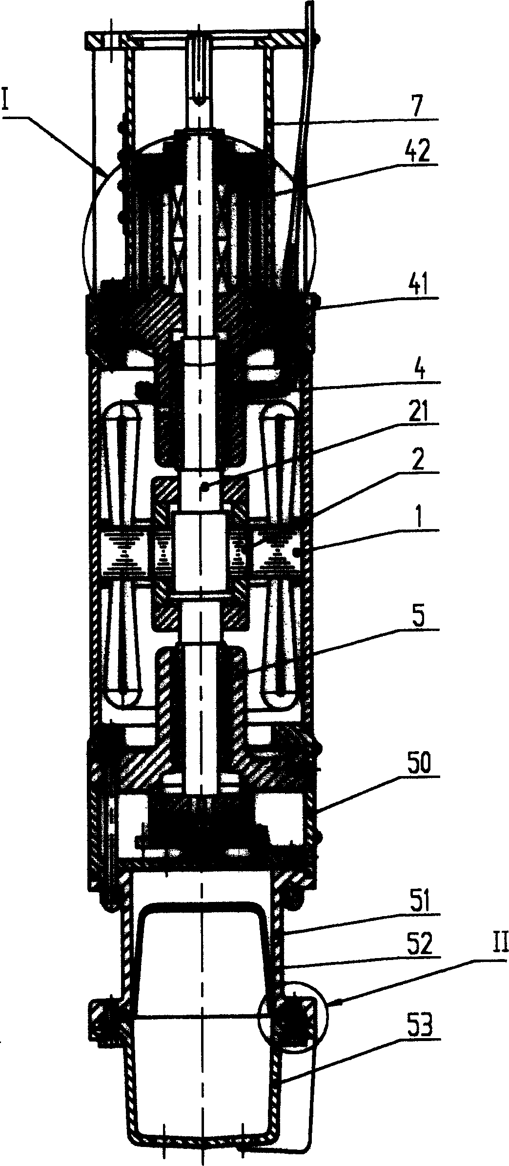
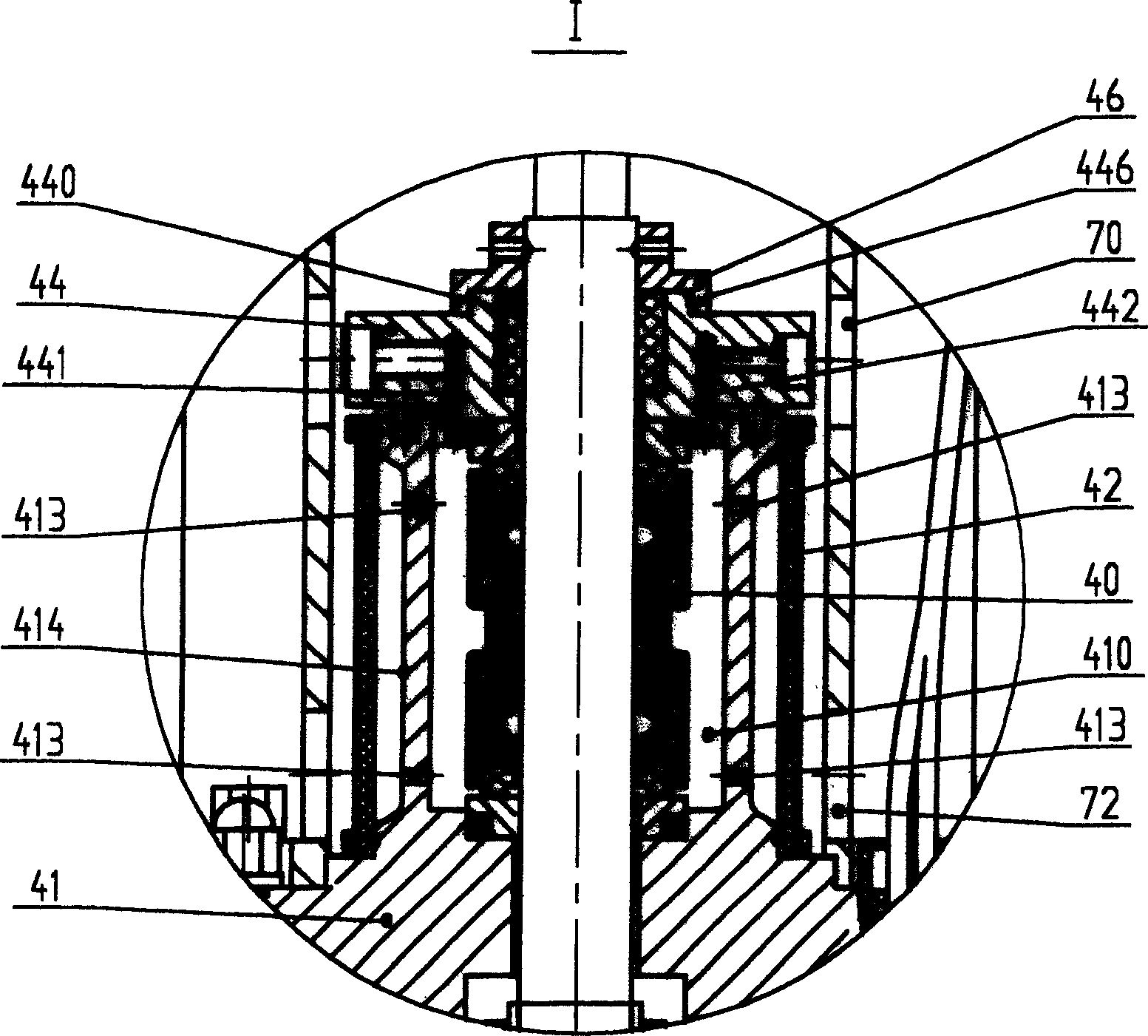
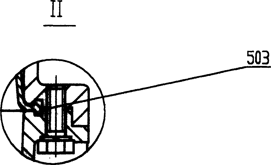
[0030] please see Figure 1-3 , a submersible motor for hot water wells, mainly composed of a flange 7, a double-end mechanical seal 40, an upper guide bearing assembly 4, a stator 1, a rotor 2, a lower guide bearing assembly 5, a thrust bearing seat 50, and a capsule bag 52 , capsule cavity 51, base 53 and other parts, it includes flange 7, upper guide bearing assembly 4, stator 1, lower guide bearing assembly 5, thrust bearing seat 50 and base 53 connected sequentially from top to bottom, and The rotor 2 is installed in the stator 1, and its rotating shaft 21 is positioned radially and axially by the upper guid...


PUM

PropertyMeasurementUnit
Elongationaaaaaaaaaa

Abstract

An immersable motor used in hot water well includes flanges connected from top to the bottom, an up guide bearing assembly, a stator, a down guide bearing assembly, a thrust bearing base and a base frame, among which, rotators are set in the stator, the thrust bearing is set on the base, the top of the up guide bearing base is set with a mechanical sealed colloid and a capsule fixed at its outside, a sealing cover is mounted on the cavity top to make up of an elastic sealed cavity, double-end-face mechanical sealings are set in the cavity, the top sealing cover is set with an oil way and a gas noz and bushes in the cover, a stop hole is mounted matched to the sand-protection cap on the top of the cover, flanges are put outside of the sealed cavity, the internal diameter of the flange is in a gap with the capsule.

Description

technical field [0001] The invention relates to a submersible motor, especially a wet submersible motor used under hot water conditions. Background technique [0002] In the known submersible motor, the shaft extension of the motor adopts a single-end mechanical seal, the interior of the motor adopts a sliding bearing system, and the stator winding adopts a magnetic wire with a plastic insulated nylon sheath. The inside of the motor with this structure is filled with water, and the motor works in water not higher than 70°C. Because the inside and outside of the motor are water media, there is no high requirement for sealing, and the plastic insulated electromagnetic wire can meet the sealing and insulation performance. With the continuous development and application of geothermal resources, the water temperature is also rising, and general submersible motors cannot adapt to it. The industry has made a lot of efforts for this. [0003] Chinese patent ...

Claims


Application Information

Patent Timeline
IPC IPC(8): H02K5/132
Inventor 李彭年张殿强李莉
Owner 天津市百利溢通电泵有限公司
Learn More