
Optical fiber strain three-dimensional simulation experimental bench

A technology for simulating experiments and optical fiber strain, applied in the direction of optical devices, measuring devices, instruments, etc., can solve the problems of difficult determination of optical fiber strain and actual stress and deformation, and inability to analyze and predict building stress and deformation

Inactive Publication Date: 2005-03-16
NANJING UNIV
View PDF0 Cites 13 Cited by
  • Summary
  • Abstract
  • Description
  • Claims
  • Application Information

AI Technical Summary

Problems solved by technology

However, the relationship between fiber strain and actual stress and deformation is difficult to determine
Therefore, if the three-dimensional simulation and calibration of optical fiber strain cannot be performed, accurate analysis and prediction of building stress and deformation cannot be made.

Method used


Image

  • Optical fiber strain three-dimensional simulation experimental bench
  • Optical fiber strain three-dimensional simulation experimental bench
  • Optical fiber strain three-dimensional simulation experimental bench

Examples


Embodiment Construction

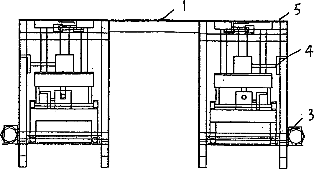
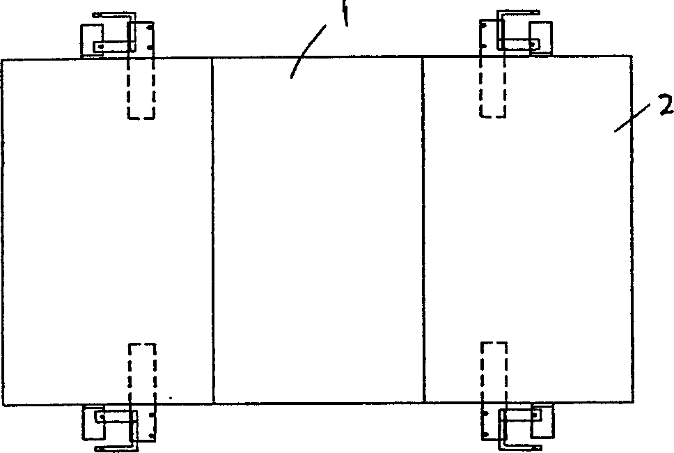
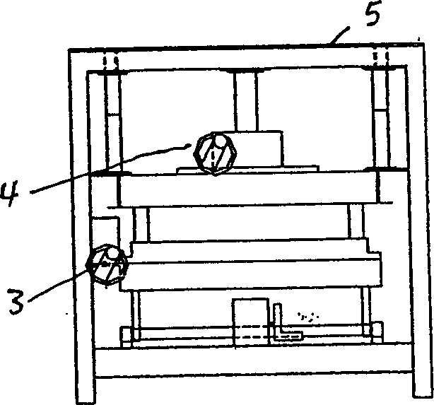
[0013] The test bench mainly consists of three independent platforms. The platform in the middle is the reference platform, and its height and angle remain unchanged. Two movable platforms are separated on both sides. The lower part of the platform is equipped with a horizontal driving part 3 and an upper and lower driving part 4. It is a three-dimensionally arranged screw handle. The spiral and the platform of the movable platform are fixed in layers, and the two movable platforms can be controlled to perform horizontal and vertical three-dimensional movements by shaking the crank under the platform. Between the platforms, a dial indicator or a dial indicator displacement measuring instrument is installed to measure the horizontal and vertical displacement, so as to organically combine the displacement with the detection results such as BOTDR.

[0014] More specifically, the driving device screw rocker of the three-dimensional motion is a worm gear 3 device, and the flat plat...


PUM


Abstract

It is an optical fiber strain three-dimensional mock test bench, which comprises separately two to three planes, wherein one of them is fixed and other each plane has at least rotary driving part that is hand or electrical crank handle. It is to drive the rotary driving part to make the plane move or slide or to move on the chute or slide board. The optical fiber is fixed on the plane and through the location of the three-dimensional move of the plane; the test bench is located with displacement meter and Brillouin diffusion light time-domain reflection meter, which make the measured signals respond to the optical fiber deformation displacement to measure the sensitivity or accuracy of the measurement to the local structure deformation of the distributed optical fiber sensor system. The test bench in this invention so can discover the layout method of the sensor optical fiber and the research of the distributed optical fiber sensor and provides necessary experiment base for the distributed optical sensor technique applied on the engineer practice.

Description

technical field [0001] The invention relates to distributed optical fiber strain sensing technology, which simulates the influence of structural deformation on distributed sensing optical fibers, and is a three-dimensional simulation experimental device for optical fiber strain, so as to test the sensitivity and performance of distributed optical fiber strain sensing technology for monitoring local deformation of structures. Accuracy, calibration of monitoring results, etc. Background technique [0002] BOTDR (Brillouin optical time-domain reflectometer), the Chinese name is Brillouin scattered light time-domain reflectometer, is a distributed optical fiber strain sensor, which can continuously measure the optical fiber strain distribution within tens of kilometers. At present, this technology has been successfully applied in the safety monitoring of buildings, tunnels, dams, slopes and other structures. Successful cases at home and abroad show that this technology has broa...

Claims


Application Information

Patent Timeline
Patent Type & Authority Applications(China)
IPC IPC(8): G01B11/16
Inventor 施斌张丹丁勇崔何亮徐洪钟高俊启王宝军索文斌
Owner NANJING UNIV
Learn More