Electrodeless discharge lamp lighting device, light bulb type electrodeless fluorescent lamp and discharge lamp lighting device
A lighting device, a technology of discharge lamps, applied in the use of discharge lamps, gas discharge lamps, electric light sources, etc., can solve problems such as incoordination
- Summary
- Abstract
- Description
- Claims
- Application Information
AI Technical Summary
Problems solved by technology
Method used
Image

Examples
Embodiment approach 1
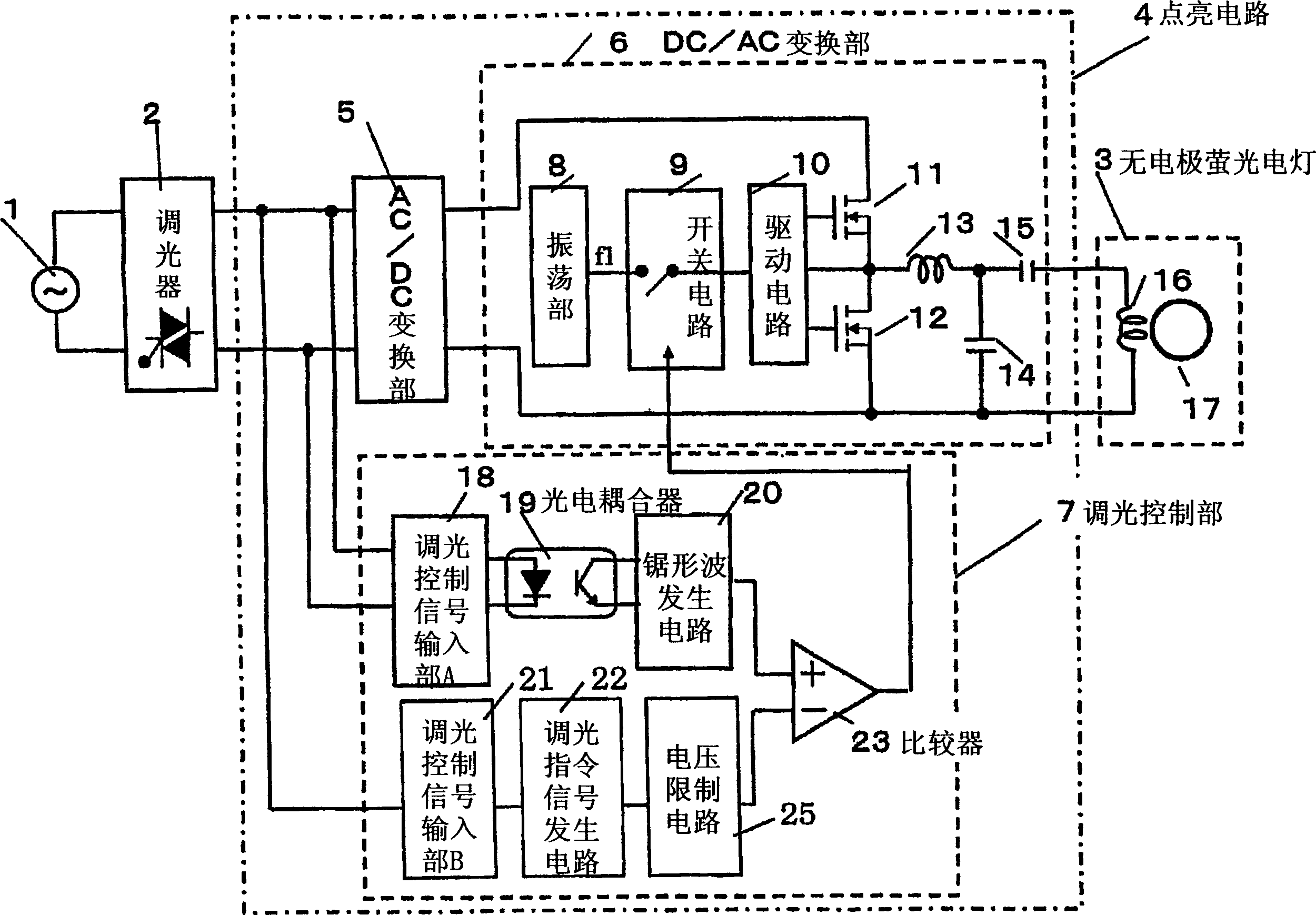
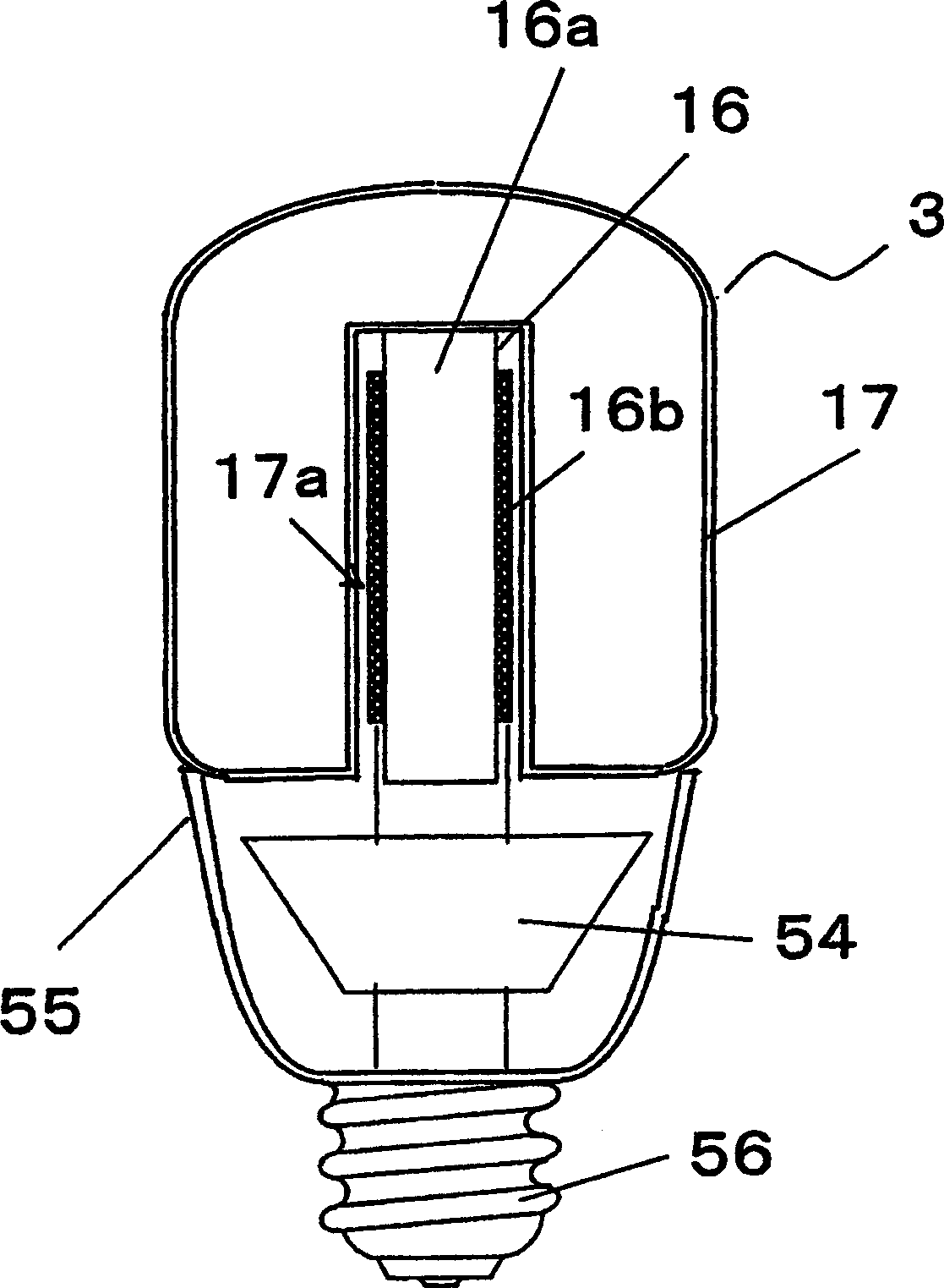
[0071] figure 1 The configuration of the discharge lamp lighting device (electrodeless discharge lamp device) according to Embodiment 1 of the present invention is schematically shown. figure 2 It is a cross-sectional view in a case where the discharge lamp lighting device according to the present embodiment is configured as an electrodeless light bulb-shaped fluorescent lamp.
[0072] The electrodeless bulb-shaped fluorescent lamp of this embodiment includes: an electrodeless fluorescent lamp 3; a lighting circuit 4 (circuit board 54) for applying a high-frequency voltage to the electrodeless fluorescent lamp 3; Lamp holder 56. exist figure 2 shown on circuit substrate 54, formed figure 1 The lighting circuit 4 is shown. Specifically, on the circuit board 54, the wiring of the configuration shown in the lighting circuit 4 is formed, and each circuit element is mounted.
[0073] like figure 2 As shown, the electrodeless bulb-shaped fluorescent lamp is integrally compo...
Embodiment approach 2
[0113] Next, Embodiment 2 of the present invention will be described with reference to FIG. 6 . The discharge lamp lighting device of this embodiment is similar to the configuration shown in the above-mentioned first embodiment, but the configuration of the saw wave generating circuit 20 that detects the on-off of the phase-controlled voltage is different from the above-mentioned first embodiment. In the configuration, it can be configured inexpensively without using an IC.
[0114] FIG. 6 shows a circuit for detecting the on-off of the phase-controlled voltage according to the present embodiment, and particularly shows the configuration of the saw wave generating circuit 20 . In addition, the same configurations as those in Embodiment 1 described above are given the same reference numerals, and redundant explanations are omitted.
[0115]The saw wave generating circuit 20 shown in FIG. 6 has a differentiating circuit 201, a diode 202, a transistor 203, and a capacitor 204, a...
Embodiment approach 3
[0121] Figure 7 It is a circuit diagram showing a discharge lamp lighting device according to Embodiment 3 of the present invention. The difference from Embodiment 1 above is that the discharge vacuum tube 17' has electrodes, and the configuration of the load resonance circuit for lighting the electrode-equipped fluorescent lamp 3' is different. In addition, the same configurations as those in Embodiment 1 described above are given the same reference numerals, and description thereof will be omitted.
[0122] The composition of this embodiment, such as Figure 7 As shown, an LC resonance circuit composed of a fluorescent lamp 3', an inductor coil 13 for resonance, a capacitor 15 for resonance, and a capacitor 14 for resonance and waste heat is connected between the drain terminal and the source terminal of MOSFET 12.
[0123] In the configuration of the present embodiment, if a high voltage as a resonance voltage is generated across the capacitor 14 of the LC resonant circu...
PUM
 Abstract
Description
Claims
Application Information
 - Generate Ideas
- Intellectual Property
- Life Sciences
- Materials
- Tech Scout
- Unparalleled Data Quality
- Higher Quality Content
- 60% Fewer Hallucinations
Browse by: Latest US Patents, China's latest patents, Technical Efficacy Thesaurus, Application Domain, Technology Topic, Popular Technical Reports.
© 2025 PatSnap. All rights reserved.Legal|Privacy policy|Modern Slavery Act Transparency Statement|Sitemap|About US| Contact US: help@patsnap.com