Mini-consumption electric controlling valve

A micro-motor and valve body technology, applied in the direction of sliding valves, valve details, valve devices, etc., can solve problems affecting gas-liquid flow, high power, and increased pressure loss, and achieve reduced impact force, simple structure, and stable precision. Effect

Inactive Publication Date: 2005-03-23
杨晖 +1
View PDF0 Cites 3 Cited by
  • Summary
  • Abstract
  • Description
  • Claims
  • Application Information

AI Technical Summary

Problems solved by technology

[0002] In the prior art, the valves sealed with planar ceramics generally have an increasing function relationship between the external force applied during the opening and closing process of the valve and the pressure of the gas and liquid in the pipeline, that is to say, the greater the pressure of the gas and liquid in t

Method used


Image

  • Mini-consumption electric controlling valve
  • Mini-consumption electric controlling valve
  • Mini-consumption electric controlling valve

Examples


Embodiment Construction

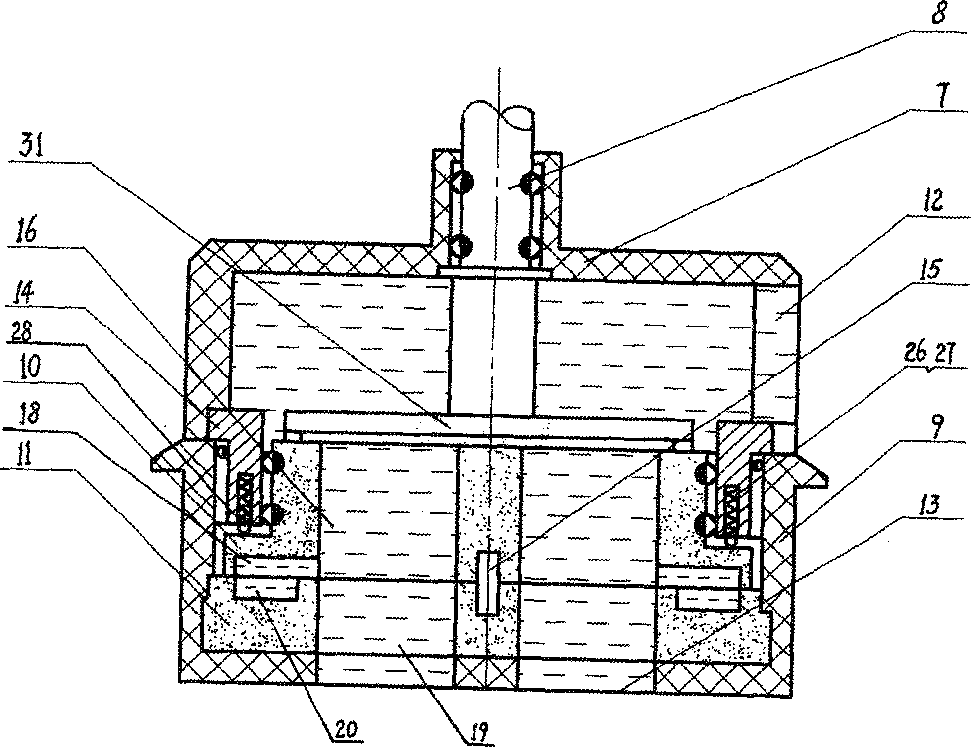
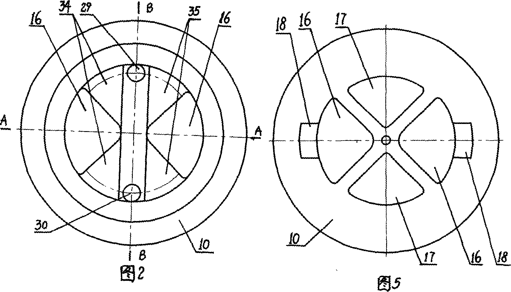
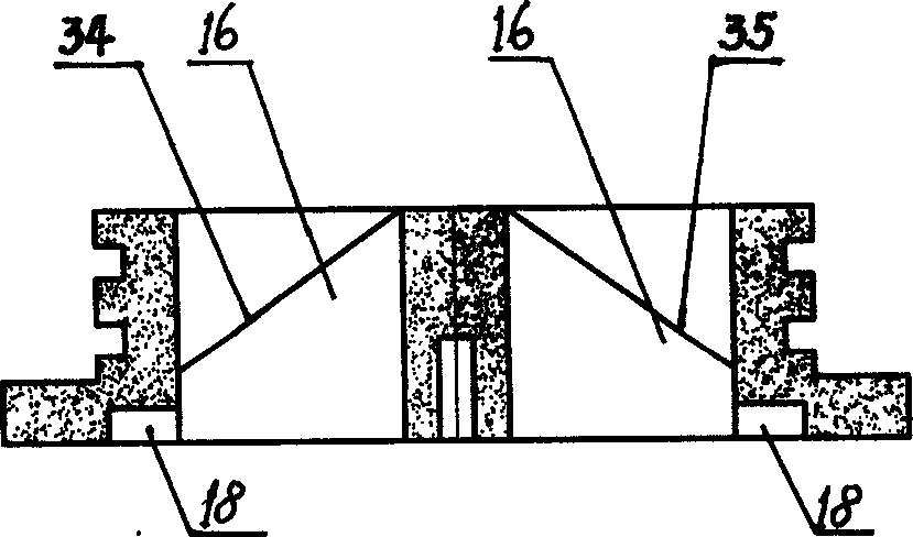
[0020] combined with figure 1 , 2, 3, 4, 5, 6, 7, 8, 9 describe an embodiment of the present invention.

[0021] An electric control valve with micro-power consumption, including a micro-motor (1), a valve body (2), a gear reduction mechanism (3), a photoelectric sensor device (4) and a positioning device (5), a micro-motor (1) and a gear The reduction mechanism (3) is arranged on the top of the valve body (2), the power input shaft of the gear reduction mechanism (3) is connected with the main shaft of the micro-motor (1), and the drive shaft (8) of the gear reduction mechanism (3) is provided with The positioning device (5), the photoelectric sensing device (4) is correspondingly arranged under the positioning device (5). The photoelectric sensing device (4) and the positioning device (5) are located in the valve body (2). The photoelectric sensing device (4) is composed of two slot-type photoelectric sensors (21) and a photoelectric sensor circuit board (22). Photoelectri...


PUM


Abstract

The invention refers to a micro power dissipation electric control valve. Driving shaft is equipped on the middle of the up bear frame. The upside of the down bear frame is equipped with motion valve plate. And the downside is fixed with fixed valve plate. The up end surface of the motion valve plate is connected to the down end surface of the driving shaft. The inter-space between the motion valve plate and the fixed valve plate is actively oriented by the central shaft of the valve plate. Blowhole and drain-hole, which are connected to fillister, are set on the motion valve plate. And blowhole and drain-hole are also set on the constant valve plate, of which the up end surface of the none-hole region is set with annular blowhole fillister and annular drain-hole fillister that connects to the fillister of the down end surface of the motion valve plate. The outer force caused by the open and close process of the invention has no direct relationship with the pressure of the air and liquid in the pipe. Thus, it can satisfy the design request of the micro power dissipation but mass flow. It has been verified that the invention could save more than 80% energy compared with the same type electric control valve driven by electric mini-motor.

Description

technical field [0001] The invention relates to a micro-power consumption electric control valve. Background technique [0002] In the prior art, the valves sealed with planar ceramics generally have an increasing function relationship between the external force applied during the opening and closing process of the valve and the pressure of the gas and liquid in the pipeline, that is to say, the greater the pressure of the gas and liquid in the pipeline, the greater the pressure of opening and closing. The power consumed by the valve is also greater, basically accounting for 95% of the entire power consumption. The usual solution is to reduce the stress area of ​​the valve plate, but this will increase the pressure loss of the valve and affect the gas-liquid flow. Contents of the invention [0003] The technical problem solved by the present invention is to design a micro-power consumption electric control valve, which adopts the principle of force balance and Pascal's la...

Claims


Application Information

Patent Timeline
IPC IPC(8): F16K3/08F16K31/04F16K31/53
Inventor 杨晖张建
Owner 杨晖
Why Eureka
Try Eureka