
Multifunction colour light indicated electronic clock

An electronic clock and multi-functional technology, applied in the field of electronic clocks, can solve the problems of inconvenient to read the time, limited digital distance, monotonous indicating color, etc., and achieve the effect of beautiful and vivid indicating effect, long visual distance and accurate timing.

Inactive Publication Date: 2005-03-23
贺明望
View PDF1 Cites 19 Cited by
  • Summary
  • Abstract
  • Description
  • Claims
  • Application Information

AI Technical Summary

Problems solved by technology

Analysis of this utility model shows that it has the following defects: 1. The "hour" display of time has adopted up to 24 digital tubes. Due to space constraints, it is impossible for this utility model to use larger digital tubes, so it can be clearly identified The distance of the numbers is very limited; 2. Since the installation position of the "hour" display digital tube corresponds to the position of the twelve equal divisions of the traditional clock dial, as long as the digital tube corresponding to the current time is illuminated, people can recognize what time it is , therefore, the numbers displayed on the nixie tubes appear redundant
3. As many as 120 LED light-emitting diodes are used for the display of "minute" and "second". This structure not only makes the composition of the clock face complicated, but also increases the cost
4. No indication or display of calendar and temperature
Analysis of this utility model shows that there are following defects: 1. It is very inconvenient to read the time at that time with a group of displays of a kind of luminous color to display hours and minutes at the same time, especially to display hours, minutes and seconds at the same time.
2. The indicator color is monotonous
3. A total of 12 CMOS integrated circuits of up to 7 different types are used in the control circuit, the structure is complex, the cost is increased, and it is inconvenient for production and maintenance
4. No indication or display of calendar and temperature

Method used


Image

  • Multifunction colour light indicated electronic clock
  • Multifunction colour light indicated electronic clock
  • Multifunction colour light indicated electronic clock

Examples


Embodiment Construction

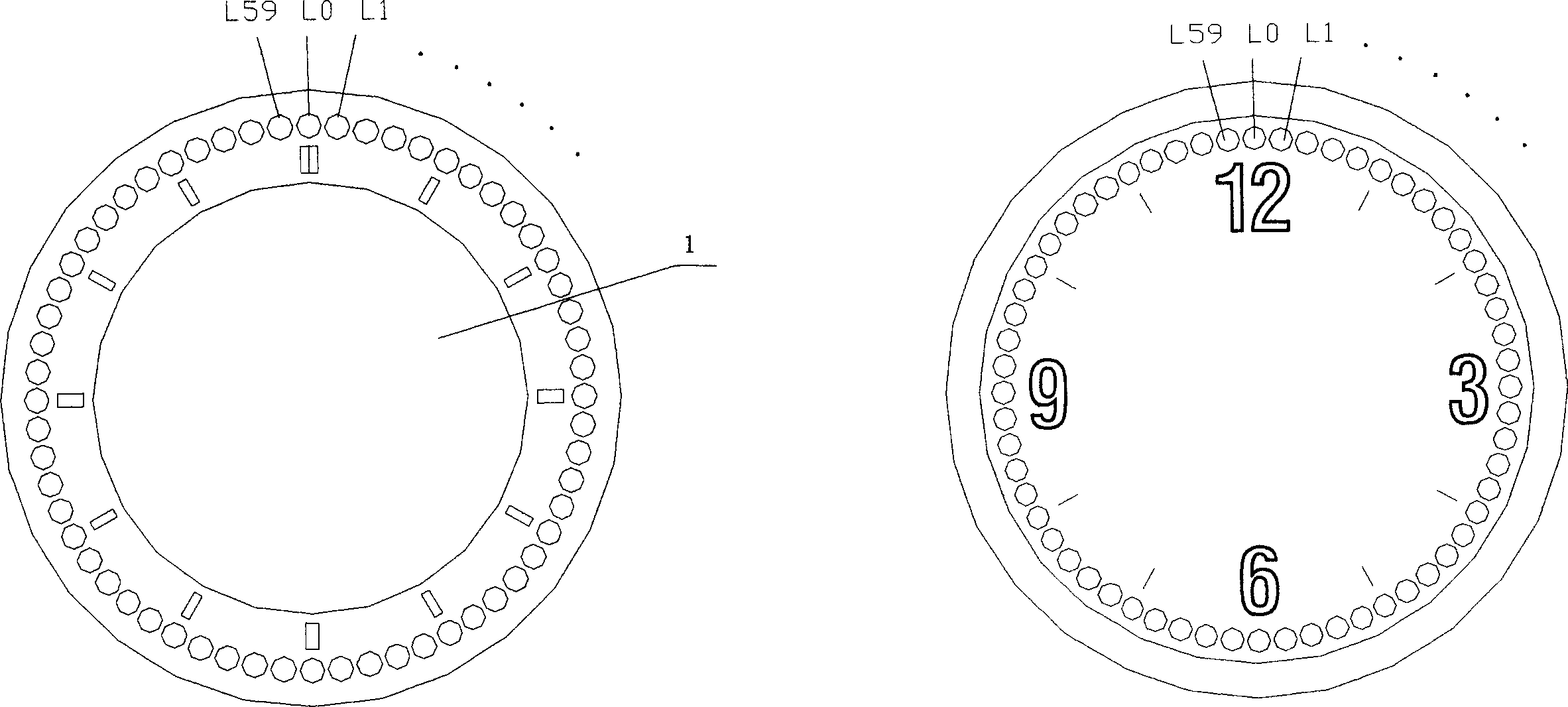
[0026] Such as figure 1 As shown, the light-emitting diodes L0-L59 are arranged clockwise in a ring, the left picture is a ring structure (the center is a hollow area), the right picture is a disc structure, and (1) in the figure is a hollow area.

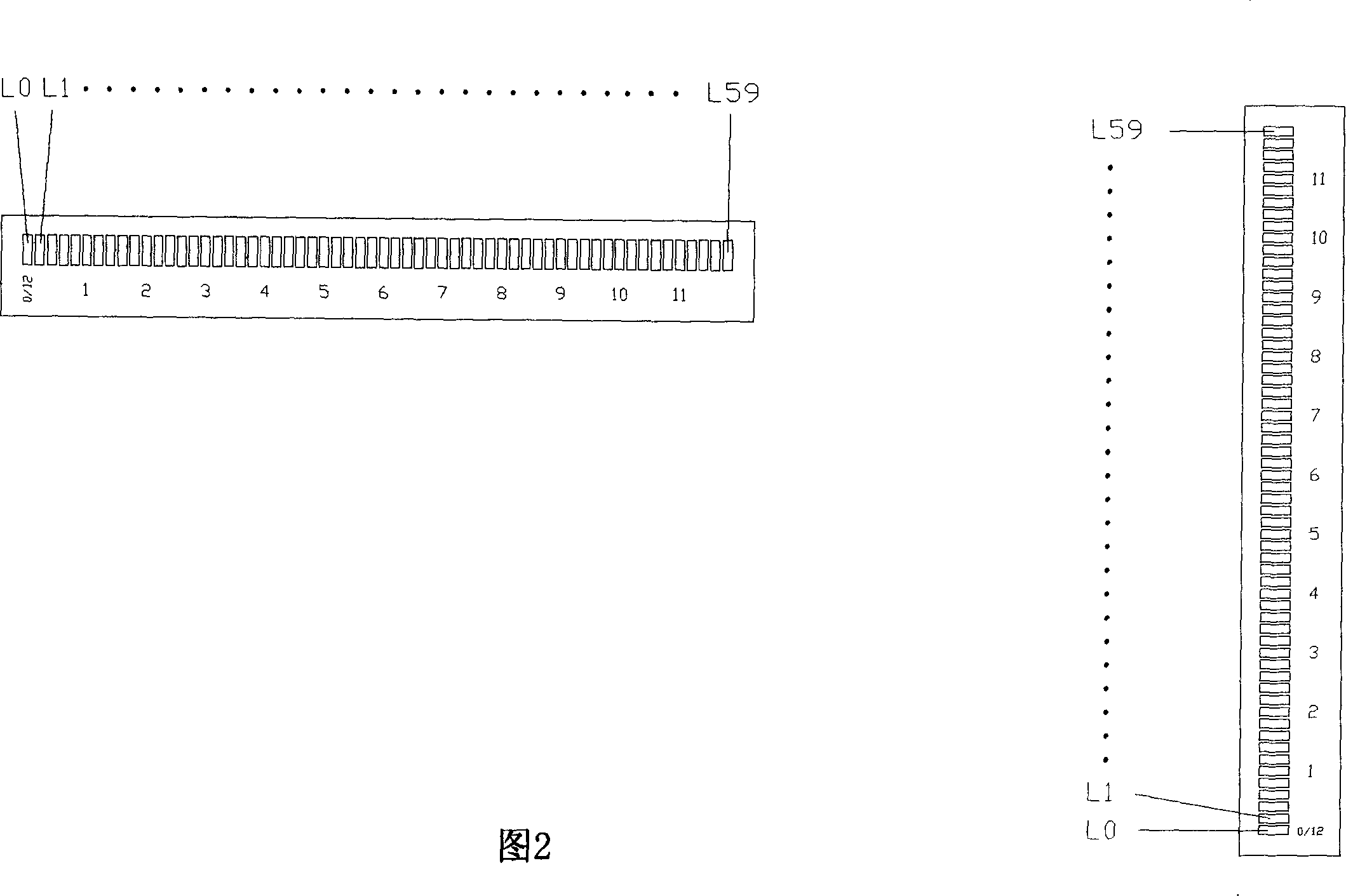
[0027] As shown in Figure 2, the light emitting diodes L0-L59 are arranged in strips, the left picture shows the horizontal arrangement type, and the right picture shows the vertical arrangement type.

[0028] Such as Figure 9 As shown, the present invention is composed of a single-chip computer, a shift register, a two-color LED array, "input and output" and a power supply, and the single-chip computer contains a control program. Among them, "input and output" refers to adjustment buttons, temperature detection, trigger signals, etc.

[0029] Such as Figure 10As shown, U1 of the present invention is an 8-bit single-chip computer AT89C2051, U2 and U3 are 8-bit serial input / parallel output shift registers 74HC164, L0-L59 are re...


PUM


Abstract

The invention discloses a multifunctional colorful light indicating electronic clock, it has 60 annular or strip double- color LEDs, which can give off three different colors. The LEDs are controlled by singlechip computer and according program to determine whether the LEDs should be shined, which color should the LEDs give off and whether the LEDs should flicker, to indicate time, date and temperature. The calendar and temperature are not displayed under normal conditions, it is generated by spring signals. The centre of the clock can be a hollow area. The invention has the characters: compact appearance, simple control circuit, no pointer, no data, the indicating effect is vivid, and the cost is low. It is suitable to living rooms, enterprises or institutions and public, especially can be manufactured to the colorful light indicating electronic clock which can be identified on frontispiece and inverse, and it is suitable to be used at station, long corridor, centre of lobby and public passageway and so on, it is also suitable to replace belfry of high building.

Description

technical field [0001] The invention relates to an electronic clock, in particular to a multifunctional colored light indicating electronic clock. Background technique [0002] In the existing clocks and watches, the expression of time can be divided into pointer type and digital type. The pointer type clock can read the hour, minute, and second of the time according to the length of the pointer, and the digital clock can only be recognized by distinguishing the number. Read the hours, minutes, and seconds of the time. [0003] Existing clocks and watches are either single-sided indication or display with a viewing angle of less than 180 degrees, or double-sided display with a reading viewing angle greater than 180 degrees, but two sets of movements or two sets of relatively high-priced display devices are required. [0004] Chinese Utility Model Patent No. 96247228 discloses "a pointerless electronic clock dial", which is composed of 12 two-digit 7-segment digital tubes di...

Claims


Application Information

Patent Timeline
IPC IPC(8): G04G9/04
Inventor 贺明望
Owner 贺明望
Learn More