Floating body for carrying persons
A floating body and hollow body technology, applied in the field of water manned entertainment equipment, can solve the problems that are not suitable for the ocean with strong waves, single gameplay, and not strong stimulation
- Summary
- Abstract
- Description
- Claims
- Application Information
AI Technical Summary
Problems solved by technology
Method used
Image
Examples
Embodiment 1
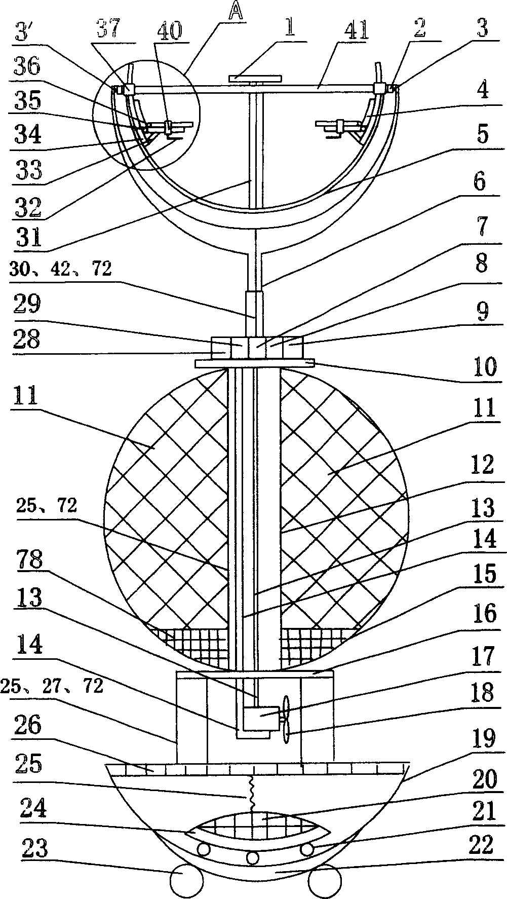
[0030] Embodiment 1: as figure 1As shown, the floating body (11) is a spherical body, the central axis of the floating body (11) has a central tube (12), and the two ends of the central tube (12) respectively have an upper plate (10) and a lower plate (16) and the center The tubes form an I-shape. Support (6) is housed on the upper plate (10), and support (6) is Y shape. The vertical part of Y-shaped support (6) is lifting rod. The inner surfaces of the two bifurcated upper ends of the Y-shaped support (6) are provided with short shafts (3, 3 '), and the universal ring (2) is installed on the short shafts (3, 3 ') on the Y-shaped support (6). ') between them; the outer surface of the universal ring (2) is provided with round holes (79, 79') corresponding to the positions of the short shafts (3, 3'), and the short shafts (3, 3') are inserted in the circle In the holes (79, 79'); the inner surface of the universal ring (2) is provided with two relative short shafts (80, 80 ')...
Embodiment 2
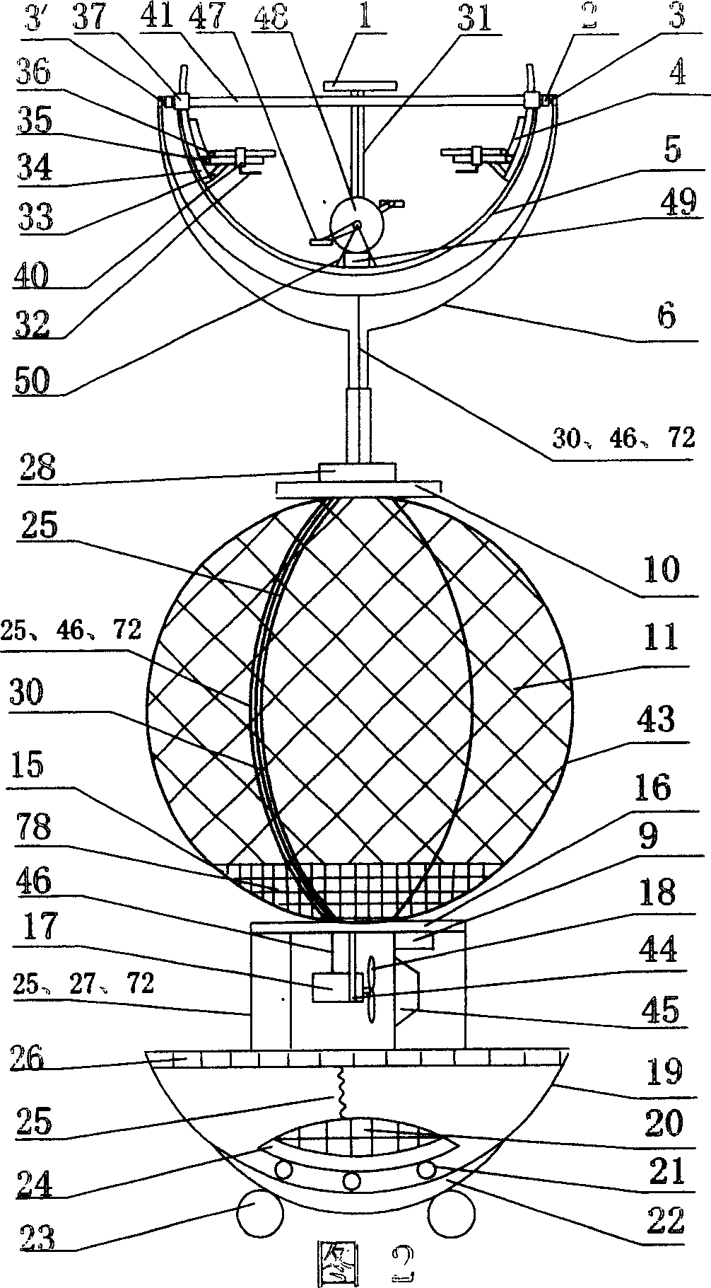
[0031] Embodiment 2: As shown in Figure 2, the structure of embodiment 2 is basically the same as that of embodiment 1, the difference is that: the connecting device is surrounded by at least three connecting straps (43) around the floating body (11), and the connecting straps ( Two ends of 43) are respectively concentrated on the two ends of the geometric central axis of the buoyant body (11), wherein an upper plate (10) is installed on one end, and a lower plate (16) is installed on the other end. The output transmission box (17) is connected to the soft transmission rod (46), and the soft transmission rod (46) is connected to the pedal transmission box (49) along the connecting belt and the Y-shaped bracket (6) along the seat (4), and the pedal transmission box (49) links to each other with roulette (48), and ottoman (47) is housed on the roulette (48), and pedal transmission box (49) and roulette (48) are supported and fixed on seat (4) by support (50). ) under the front. ...
Embodiment 3
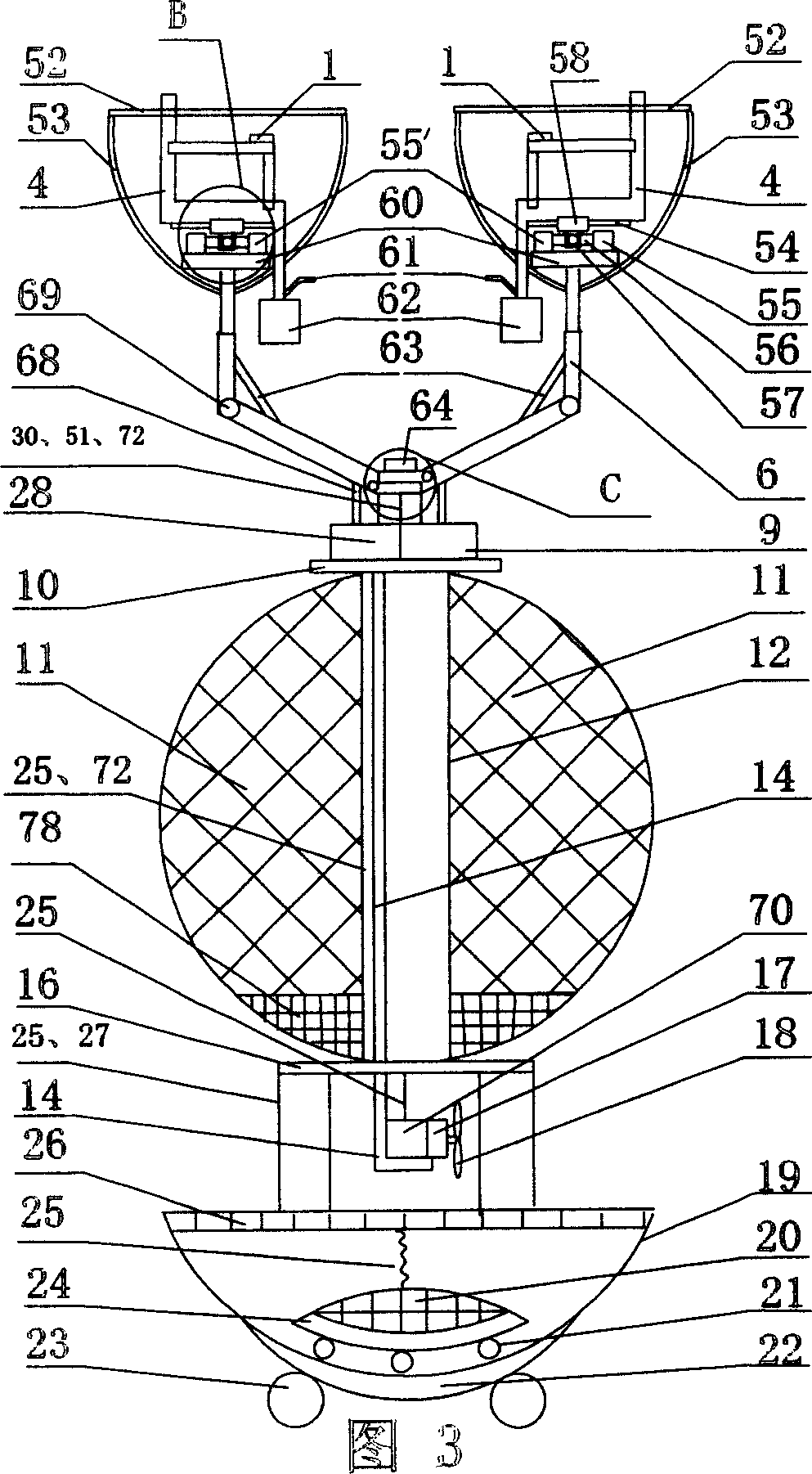
[0032] Embodiment 3: As shown in Figure 3, the structure of Embodiment 3 is basically the same as that of Embodiment 1, the difference is that: the bracket (6) is L-shaped and installed on the central axis (64) of the upper plate (10) On, there are two rotating rings (65) on the central shaft (64) upper end, and the rotating control lever button (66) is arranged on the rotating ring (65). The L-shaped support (6) is connected with the rotating ring (64) by the connecting shaft (67), and the telescopic rod (68) is used to adjust the angle between the support and the central axis (64). There is another shaft joint (69) at the position, and the telescopic rod (63) is used to adjust the angle between the horizontal rod and the longitudinal rod of the support (6); the longitudinal rod itself can be lifted; the upper end of the L-shaped support (6) longitudinal rod There is a seat (4) facing the extension line of the central axis, and the bottom surface of the seat (4) is provided w...
PUM
 Abstract
Description
Claims
Application Information
 - R&D
- Intellectual Property
- Life Sciences
- Materials
- Tech Scout
- Unparalleled Data Quality
- Higher Quality Content
- 60% Fewer Hallucinations
Browse by: Latest US Patents, China's latest patents, Technical Efficacy Thesaurus, Application Domain, Technology Topic, Popular Technical Reports.
© 2025 PatSnap. All rights reserved.Legal|Privacy policy|Modern Slavery Act Transparency Statement|Sitemap|About US| Contact US: help@patsnap.com


