Eureka AIR delivers breakthrough ideas for toughest innovation challenges, trusted by R&D personnel around the world.

Flyback power converter

A technology of power converter and power transformer, which is applied in the direction of output power conversion device, DC power input conversion to DC power output, instruments, etc. It can solve the problems of increasing peak output current, increasing ripple, and not being able to prohibit output, etc., to achieve Effect of Reducing Turn-On Loss

Inactive Publication Date: 2005-03-30
KONINKLIJKE PHILIPS ELECTRONICS NV
View PDF3 Cites 13 Cited by
  • Summary
  • Abstract
  • Description
  • Claims
  • Application Information

AI Technical Summary

Problems solved by technology

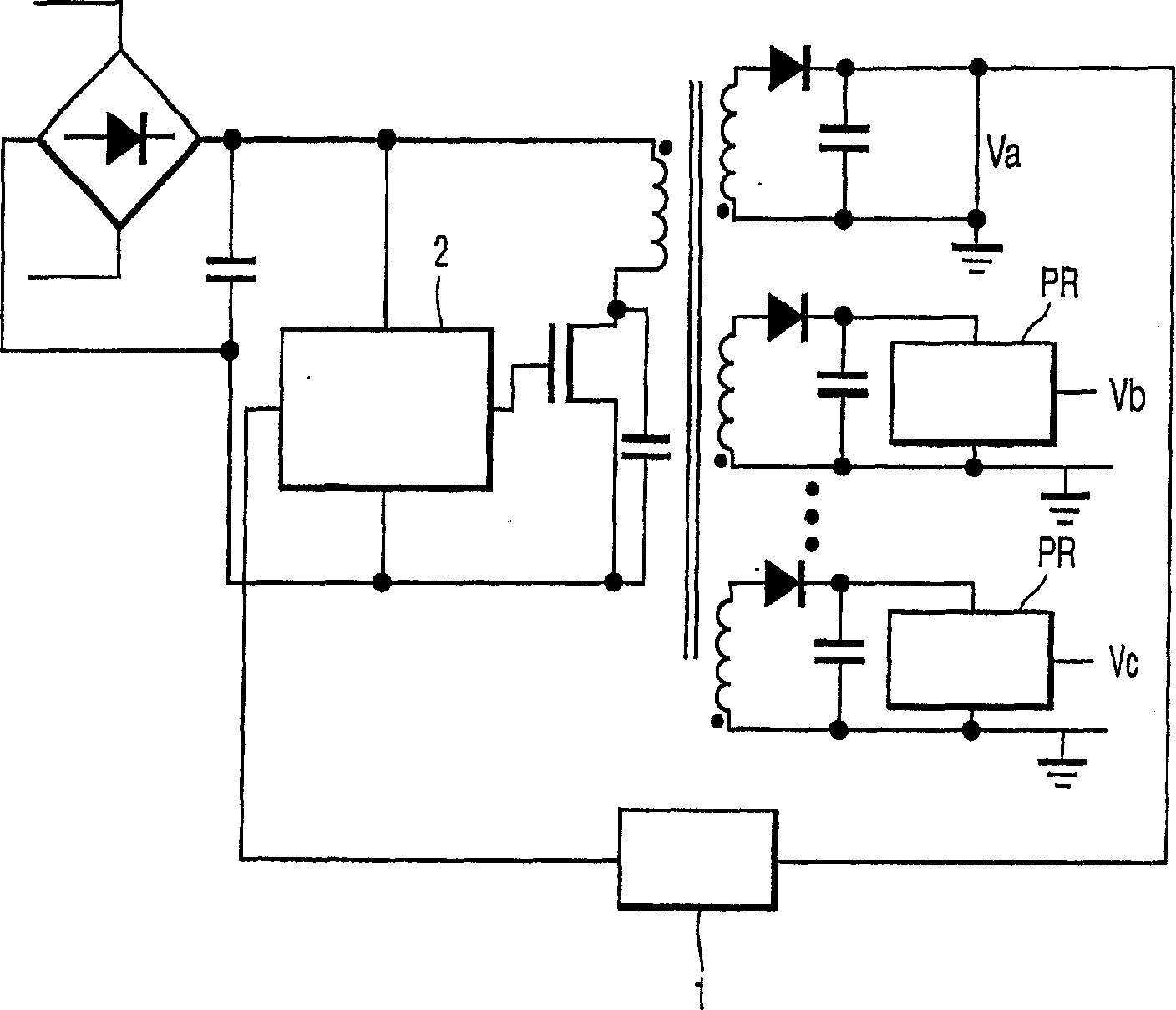
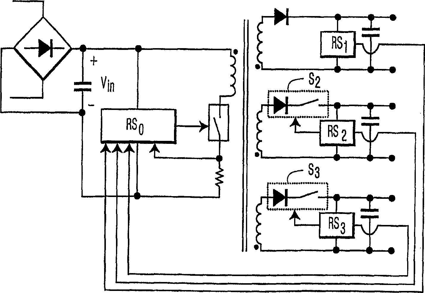
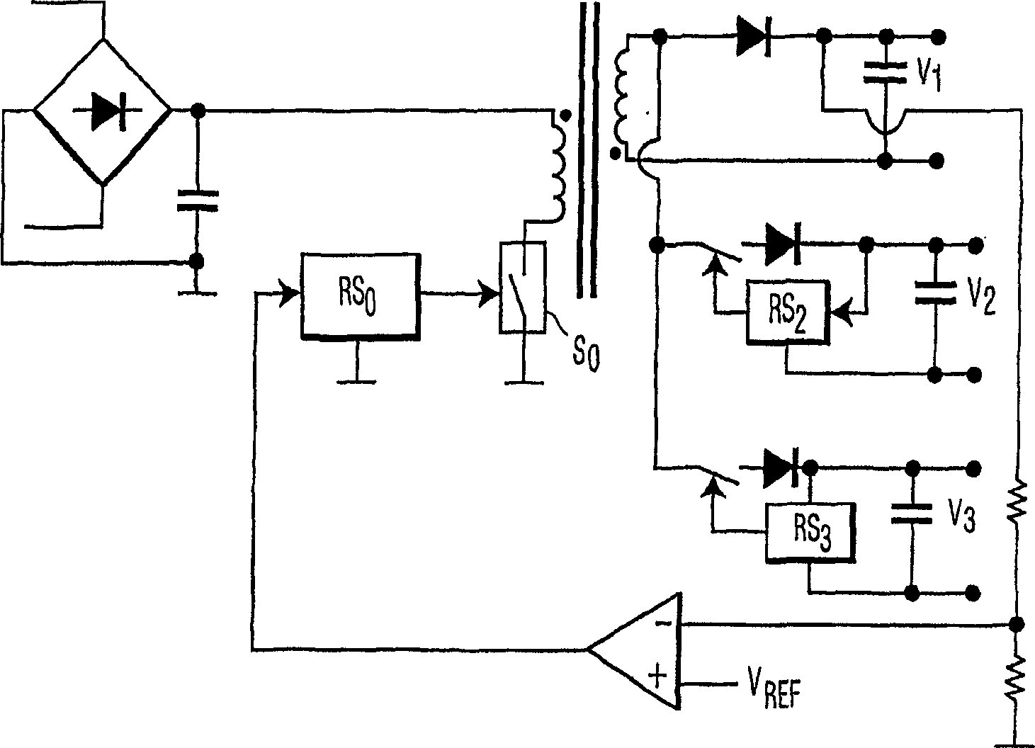
This effect cannot be achieved using the circuit configurations of Figures 2 and 3, because those outputs that do not include the secondary switch cannot be disabled without disabling all outputs
[0012] Another disadvantage related to the circuit of Figure 4 is that the regulation method described here increases the peak output current, which results in increased ripple compared to the method of continuously supplying current to multiple outputs

Method used


Image

  • Flyback power converter
  • Flyback power converter
  • Flyback power converter

Examples


Embodiment Construction

[0029] refer to Figure 5 , shows a schematic diagram of an example of a flyback converter circuit, generally indicated by numeral 500, according to the present invention. The converter 500 includes a primary circuit 505 , a regulated output circuit 510 and an optocoupler 520 . The optocoupler 520 optically couples the feedback signal from the power-isolated regulated output circuit 510 to the non-power-isolated primary circuit 505 . The primary side circuit 505 consists of a power switch connected to the S 0 The primary coil 514 of the transformer T is connected to the input capacitor C across the first and second input power supply nodes 4 and primary side controller 507, the capacitor C 4 A rectified input voltage V is present across the in. The primary side controller 507 via the gate V G0 Control switch S 0 , the gate V G0 is the power switch S 0 the control terminal. Switched capacitor C 5 and power switch S 0 in parallel. When the power switch S 0 When turn...


PUM


Abstract

A power converter (500) is described which provides multiple independently regulated outputs (T<1>, T<2>, T<3>). Zero-volt primary side switching is achieved at a resonance minimum which occurs at the end of each energy cycle as result of a resonant condition between a switch capacitor (C<5>) and a primary winding (514) of an isolation transformer (T).

Description

technical field [0001] The present invention relates generally to power conversion and, more particularly, to multiple output flyback converters. Background technique [0002] Power converters are widely used to provide the required voltage and load current, especially in more concentrated environments of communication or computer equipment. These power converters often need to provide high levels of output power in a small physical size, since space is often at a premium. This requirement indicates that the power converter is a high power density device. These higher power density concentrations also indicate that the power converter is operating as efficiently as possible in order to minimize the heating of the converter and thereby minimize its operating temperature rise. [0003] By using switching regulator technology, higher power converter efficiencies can be obtained than using linear regulation technology. However, these switching regulator technologies introduce...

Claims


Application Information

Patent Timeline
Patent Type & Authority Applications(China)
IPC IPC(8): H02M3/28H02M3/335
CPCH02M3/33561Y02B70/1433Y02B70/10H02M3/335
Inventor D·J·吉安诺波洛斯
Owner KONINKLIJKE PHILIPS ELECTRONICS NV
Why Eureka
Eureka Blog
Learn More