Suspension apparatus for a vehicle and vehicle including same

一种横向稳定杆、安装结构的技术,应用在车辆部件、运输和包装、装在枢轴上的悬臂等方向,能够解决设计自由度减少、成本增加、上支臂202形状复杂等问题,达到增加设计自由度、简化形状、改善装配性能的效果

Inactive Publication Date: 2005-04-06
HONDA MOTOR CO LTD
View PDF1 Cites 19 Cited by
  • Summary
  • Abstract
  • Description
  • Claims
  • Application Information

AI Technical Summary

Problems solved by technology

[0007] In addition, if the mounting portion of the stabilizer 208 is set on the upper arm 202, or the mounting portion of the rigid body 201 between the upper arm 202 and the lower arm 203 is provided, the shape of the upper arm 202 will be Becomes more complex, resulting in increased cost, and, limited by the shape of the upper arm, reduces design freedom

Method used


Image

  • Suspension apparatus for a vehicle and vehicle including same
  • Suspension apparatus for a vehicle and vehicle including same
  • Suspension apparatus for a vehicle and vehicle including same

Examples


Embodiment Construction

[0030] Hereinafter, preferred modes for carrying out the present invention will be described with reference to the drawings. In addition, the drawings are views from the directions indicated by the symbols.

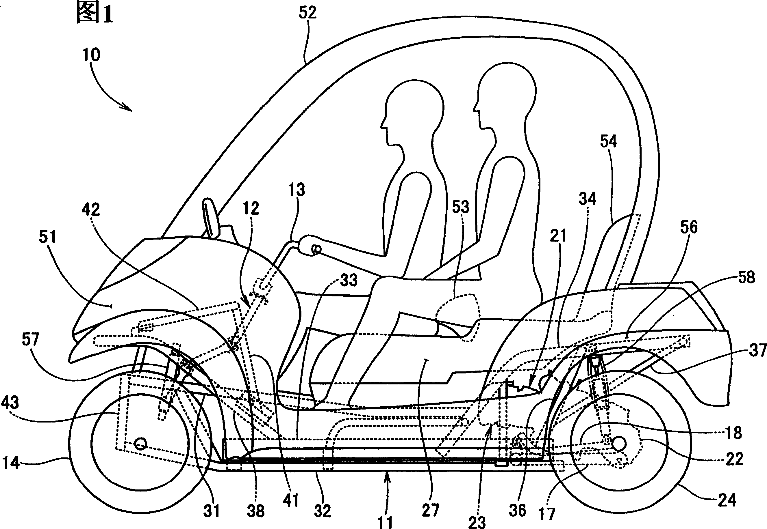
[0031] Fig. 1 is the side view of the vehicle involved in the present invention, vehicle 10 is a two-person passenger four-wheeled vehicle, by installing split steering shaft 12 at the front portion of vehicle body frame 11, and installing handle 13 at the top of steering shaft 12, Manipulate the left and right front wheels 14,15 (only showing the label 14 in front of the figure), the rear portion of the vehicle body frame 11 is installed by the engine 21 and the speed changer 22 integrally installed with the rear portion of the engine. The power unit 23 of this power unit 23 is equipped with rear wheels 24,26 on the output shaft of the power unit 23 (only showing the label 24 in front of the figure), and the double seat 27 is installed on the top of the vehicle body fram...


PUM


Abstract

A vehicle is constituted such that suspension arms 72, 72 are mounted to the right and left of a vehicle body frame 11, a knuckle arm 112 is installed to the suspension arms 72, 72 a front cushion unit 57 is set over between the body frame side and the suspension arm side, and that an anti-roll bar device 82 to suppress the rolling of the body is set over to the suspension arm sides, wherein the anti-roll bar device 82 is set over to right and left supporting members 77, 77 installed to tips of the suspension arms 72, 72 coupled with the knuckle arm 112, and supporting the end of the front cushion unit 57 on the side with the suspension arms 72, 72. To reduce cost by simplifying shapes of suspension arms and widen the degree of freedom in designing the suspension arms without increasing stiffness particularly for mounting an anti-roll bar device.

Description

technical field [0001] The invention relates to a mounting structure of a vehicle lateral stabilizer bar device. Background technique [0002] Conventionally, as a vehicle stabilizer device mounting structure, it is known that a stabilizer is erected between left and right upper arms constituting a V-shaped hanger. (For example, see Patent Document 1). [0003] [Patent Document 1] JP-A-3-213414 [0004] through the next Figure 8 For Patent Document 1 figure 2 Be explained. And change the label. [0005] Figure 8 It is an explanatory diagram showing the installation structure of a conventional vehicle stabilizer bar device. As shown in the figure, an upper arm 202 and a lower arm 203 are installed on a vehicle frame 201 so as to be able to swing freely. The front end of support arm 203 is equipped with articulated arm 204, on articulated arm 204, wheel 206 is installed freely rotatable, by joint 207,207 (only shows one side label 207) on left and right upper support a...

Claims


Application Information

Patent Timeline
Patent Type & Authority Applications(China)
IPC IPC(8): B60G1/00B60G3/20B60G7/00B60G21/055
CPCB60G2204/129B60G2204/43B60G3/20B60G7/001B60G2200/44B60G2204/1224B60G2204/416B60G2204/422B60G2200/144B60G21/0551B60G2206/11
Inventor 关文三
Owner HONDA MOTOR CO LTD
Why Eureka
Try Eureka