Solar battery automatic coating system

A solar cell, automatic technology, applied in the direction of circuits, photovoltaic power generation, electrical components, etc., can solve the problem of no solar cell square array automatic patching system, etc., to improve labor production efficiency, reduce production costs, and reduce the effect of fragmentation rate.

Inactive Publication Date: 2005-04-06
SHANGHAI JIAO TONG UNIV
View PDF1 Cites 10 Cited by
  • Summary
  • Abstract
  • Description
  • Claims
  • Application Information

AI Technical Summary

Problems solved by technology

At present, there is a blank in the field of automatic placement of solar ...

Method used


Image

  • Solar battery automatic coating system
  • Solar battery automatic coating system
  • Solar battery automatic coating system

Examples


Embodiment Construction

[0020] The technical solution of the present invention will be further described below in conjunction with the accompanying drawings.

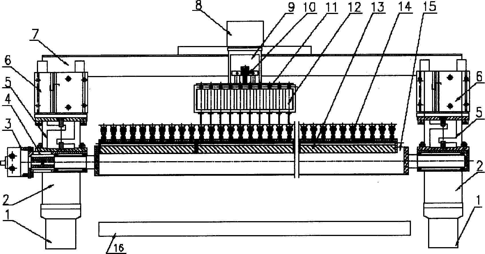
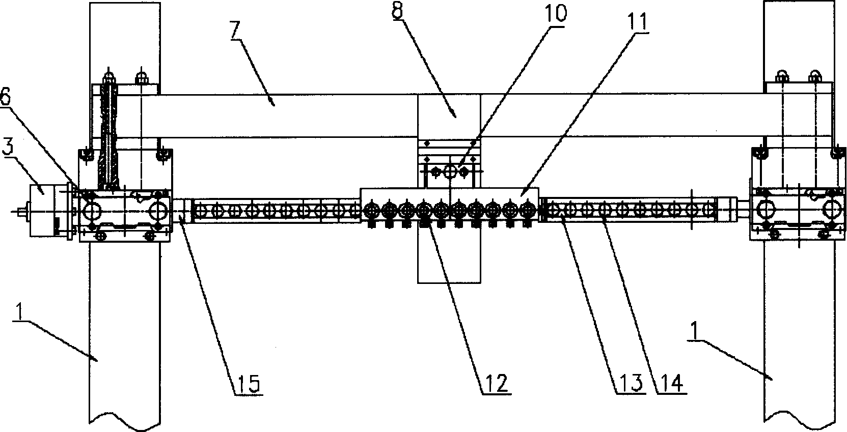
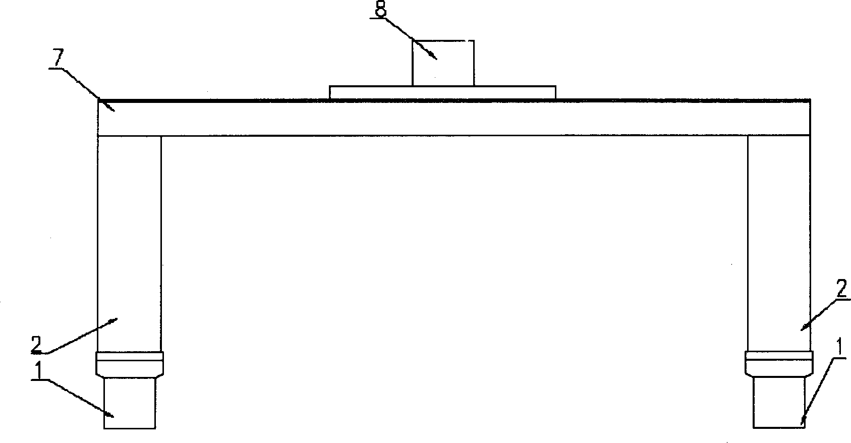
[0021] The overall structure of the solar cell automatic placement system of the present invention is as follows: figure 1 (main view), figure 2 (top view), as shown, it is guided by the positioning mechanism ( image 3 ), cloth sticking mechanism ( Figure 4 ), dispensing mechanism ( Figure 5 )composition.

[0022] figure 1 It is the front view of the overall structure of the solar cell automatic placement system. The bottom of the figure is two X-guiding rails 1, and a support beam 2 is installed on the slider of each X-guiding rail 1. On the top of the two support beams 2 A Y-guiding rail 7 is fixed, and a Z-guiding rail 8 is installed on the slider of the Y-guiding rail 7; an executive cylinder 6 is respectively fixed in front of the upper part of the two support beams 2, and a puller is respectively connected and fixed below the tw...


PUM


Abstract

This invention relates to a solar cell automatic label system. The guide position structure is composed of three freedom degree guide rail and the label structure is fixed on the supportive beam of the guide position structure composed of executive cylinder, sensor, swing cylinder, connection part, base part, acetabula chassis. The two executive cylinders down sensor is fixed on the connection. The glue drop structure is fixed on the slide block down part of Z guide rail composed of supportive plate, micro-adjusting structure, fixed frame and glue-drop needle.

Description

technical field [0001] The invention relates to an automatic placement system for solar cells, which is an automatic placement robot system capable of automatically placing solar cells on solar panels, and belongs to the technical field of IC post-packaging. Background technique [0002] The solar cell phalanx is one of the important components for the normal operation of space satellites. How to paste the packaged solar cell cloth on a large-area sailboard to make a solar cell array is a complicated and meticulous work, because the solar cell is small, thin, light, and brittle, and the solar cell The battery array usually has a large area. At present, the production of solar battery arrays in China is completely done by hand, which not only has low work efficiency, but also has a high fragmentation rate. Usually, skilled workers with industry work experience are required to operate this process, and It is difficult to guarantee the consistency, reliability and aesthetics of ...

Claims


Application Information

Patent Timeline
IPC IPC(8): H01L21/50H01L31/18H02S20/30
CPCY02E10/50Y02P70/50
Inventor 吴跃新赵言正付庄曹其新陈鸣波唐则祁
Owner SHANGHAI JIAO TONG UNIV
Why Eureka
Try Eureka