Antenna system

An antenna system, technology covering antennas, applied in the direction of antennas, antenna arrays, antenna components, etc.

Inactive Publication Date: 2005-04-06
ANDREW CORP
View PDF5 Cites 26 Cited by
  • Summary
  • Abstract
  • Description
  • Claims
  • Application Information

AI Technical Summary

Problems solved by technology

The problem with this phased array technique is that there are unavoidable tradeoffs

Method used


Image

  • Antenna system
  • Antenna system
  • Antenna system

Examples


Embodiment Construction

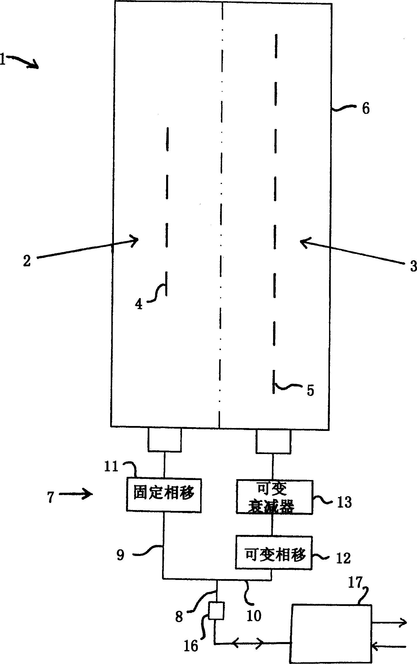
[0024] reference figure 1 , A single-polarized antenna system 1 includes a cover antenna 2 and an auxiliary antenna 3. The cover antenna includes one vertical line of four vertically oriented dipoles 4, and the auxiliary antenna includes one vertical line of eight vertically oriented dipoles 5 parallel to and side by side of the dipole 4. Only the lowest dipole of the two antennas is labeled 4 and 5.

[0025] The dipole is mounted on a panel 6 that acts as both a back reflector and an RF ground plane. The dipole and the panel 6 are enclosed in a single antenna shield (not shown). The package width is about 300mm. Other package widths can also be used, depending on the wavelength of operation.

[0026] The antennas 2 and 3 are driven by a feed network 7 which includes a main feeder 8, an overlay antenna feeder 9 and an auxiliary antenna feeder 10. The feeders 9 and 10 meet the main feeder 8 at the intersection. A fixed phase shifter 11 is added to the cover antenna feed line 9. Th...


PUM


Abstract

An antenna system including a coverage antenna (2) with a coverage beam pattern; and an auxiliary antenna (3) with an auxiliary beam pattern. The auxiliary beam pattern is arranged to perform sidelobe suppression, null steering, null addition, or null-fill. In the case where the auxiliary antenna is used to perform sidelobe suppression, the auxiliary beam pattern has a mainlobe with: an amplitude lower than an amplitude of a mainlobe of said coverage beam pattern; a width lower than a width of said mainlobe of said coverage beam pattern; a phase different to a phase of a sidelobe of said coverage beam pattern; and a direction which is selected so as to at least partially suppress said sidelobe.

Description

Technical field [0001] The present invention relates to an antenna system, which is typically but not exclusively applied to mobile communication wireless networks. Background technique [0002] It is often found that the capacity of wireless networks is limited by interference. These interferences mainly come from the nearest neighboring cells that use the same frequency. This problem is caused by Picture 10 Note that it shows a vertical area passing through the first base station 50 and the nearest neighboring base station 51. Each base station has an antenna with its own main lobes 52, 53, first upper side lobes 54, 55, and second upper side lobes 56, 57. From Picture 10 Looking at the downward inclination angle in the middle, it can be seen that the first upper side lobes 54, 55 are horizontal. As a result, the side lobe 55 appears as an interference source to the receiving channel of the base station 50, and the side lobe 54 appears as an interference source to the receivi...

Claims


Application Information

Patent Timeline
Patent Type & Authority Applications(China)
IPC IPC(8): H01Q1/24H01Q3/26
CPCH01Q1/246H01Q3/2629
Inventor R·D·埃利奥特K·E·莱恩汉
Owner ANDREW CORP
Why Eureka
Try Eureka