Ultrasonic motor for monitor cradle

An ultrasonic motor and monitor technology, applied in the direction of generators/motors, electrical components, piezoelectric effect/electrostrictive or magnetostrictive motors, etc., can solve problems such as winding, and achieve reliable transmission and stable support movement Effect

An ultrasonic motor and monitor technology, applied in the direction of generators/motors, electrical components, piezoelectric effect/electrostrictive or magnetostrictive motors, etc., can solve problems such as winding, and achieve reliable transmission and stable support movement Effect

CN1606225AInactive Publication Date: 2005-04-13JIANGSU FENGKE ULTRASONIC MOTORS TECH

Image

  • Ultrasonic motor for monitor cradle
  • Ultrasonic motor for monitor cradle
  • Ultrasonic motor for monitor cradle

Examples


Embodiment Construction

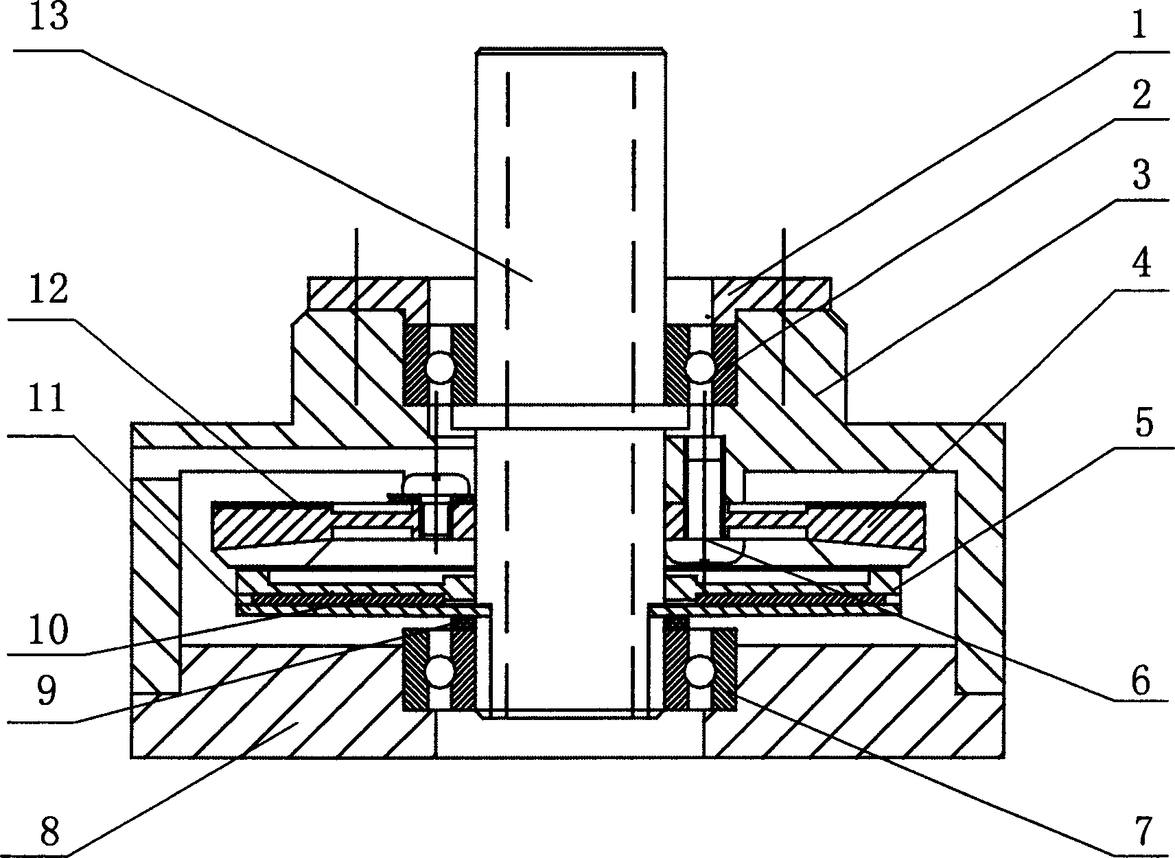
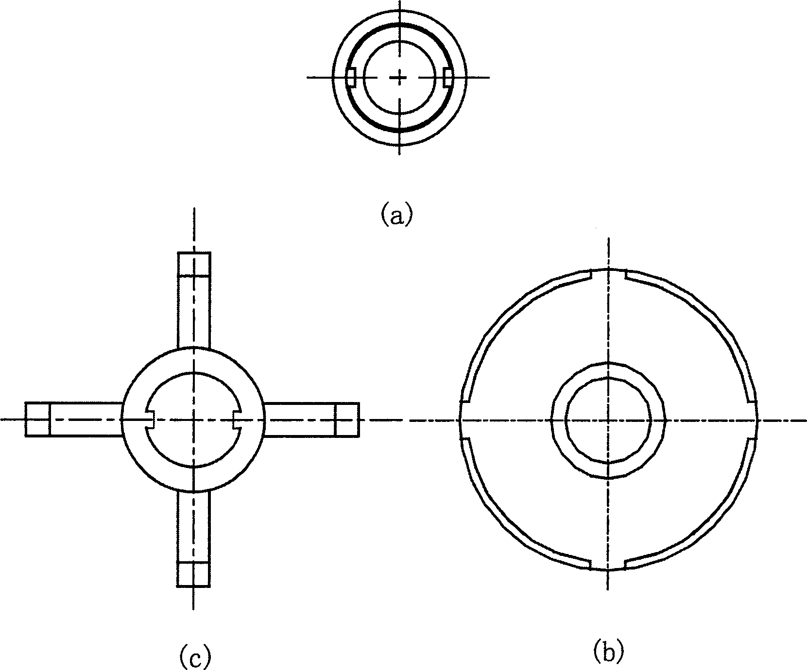
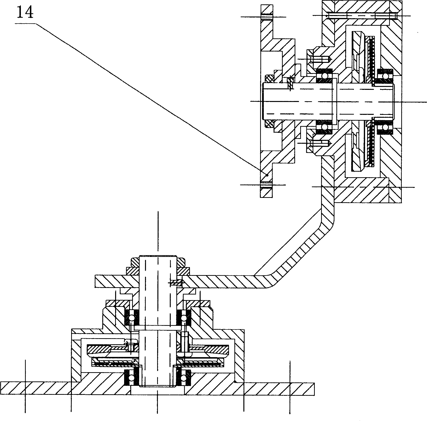
[0009] As can be seen from Figure 1, the structure of the ultrasonic motor used for a single monitor pan / tilt is that the bearing cap 1 is connected to the upper end surface of the housing 3 by screws, the piezoelectric ceramic sheet 12 is pasted on the upper surface of the stator 4, and the stator 4 is placed in the housing. The body is installed on the boss in the middle of the upper end of the housing 3 through screws, the rotor placed under the stator 4 is fixed on the output shaft 13, and the spring leaf 11 installed on the output shaft is placed between the rotor 5 and the gasket 10, The upper and lower ends of the output shaft 13 are respectively supported by bearings on the bearing 1 and the base 8 to make the movement more stable and reliable. The output shaft 13 is hollow and can pass through wires, which solves the problem of winding when the pan / tilt rotates. The outer diameter of the shaft has a pair Symmetrical keyway, as shown in figure (a) in Figure 2. There is...


PUM


Abstract

A monitor supersonic motor is composed of a rotor, a stator, spring plate, a hollow shaft, piezoelectric ceramic plates, the stator is fixed at the shell by screws, the rotor generates a pressure to press on the stator relying on the deformation of the spring plate, adjustment of pad thickness determines the deformation volume of the spring and the pre-pressure. The rotor and the spring, the spring and the shaft are driven by keyslot connection and the shaft applies a clamped way for bearings at both ends. When a sine- exciting signal with two-phase difference of 90deg.is inlet into the ceramic plate on the stator, mass points on its surface move elliptically to drive the rotor.

Description

Technical field: [0001] The ultrasonic motor for monitor pan-tilt of the present invention belongs to the ultrasonic motor in the field of micro motors. Background technique: [0002] Ultrasonic motor is a new type of micro motor using the inverse piezoelectric effect of piezoelectric ceramics and ultrasonic vibration. The patent No. ZL 98 1 11421.0 has poor reliability and stability due to the use of friction transmission, and is also not suitable for application on the monitor pan / tilt. Invention content: [0003] The purpose of the present invention is to develop a traveling-wave ultrasonic motor suitable for monitor pan-tilts with low speed, simple structure, fast response speed and hollow output shaft. [0004] The composition of the ultrasonic motor is that the bearing cover is connected to the upper end surface of the housing, the lower end surface of the housing is in contact with the base, the stator with piezoelectric ceramic sheets pasted on the surface is plac...

Claims


Application Information

Patent Timeline
13 Apr 2005
Publication
CN1606225A
IPC
H02N2/10
Inventors
赵淳生; 梁操