
Combined powder selector with double wheel differential motion

A technology of powder classifier and roulette, which is applied in the direction of solid separation, separating solid from solid by air flow, chemical instruments and methods, etc. It can solve the problems of inability to operate at differential speed, complex system, and low efficiency of powder selection.

Inactive Publication Date: 2005-04-20
何正凯
View PDF1 Cites 6 Cited by
  • Summary
  • Abstract
  • Description
  • Claims
  • Application Information

AI Technical Summary

Problems solved by technology

This powder classifier has the advantages of simple system, short air path, and small resistance along the air path, but the biggest disadvantage is that the large blades, small blades and the spreading disc are driven by the same shaft, and cannot be operated at differential speeds, making it difficult to adapt to different productions. The situation has different needs for them, resulting in low powder selection efficiency
[0004] The second-generation cyclone-type powder separator and the third-generation rotating cage-type powder separator generate air for classification by peripheral fans. The cyclone-type powder separator operates at low wind speed and low blade resistance to slow down energy consumption. The increase of resistance along the road increases the efficiency of powder selection to a limited extent
The rotary cage type powder separator operates under the condition of high wind speed and high resistance of small blades, and the powder selection efficiency is significantly increased, but the energy consumption of the system to overcome the resistance along the wind path also increases significantly, offsetting most of the Due to the increase in powder selection efficiency and the energy consumption saved by increasing production (the entire grinding system), the reduction in energy consumption of the entire system is limited, and the system is complex

Method used


Image

  • Combined powder selector with double wheel differential motion
  • Combined powder selector with double wheel differential motion
  • Combined powder selector with double wheel differential motion

Examples


Embodiment Construction

[0009] The implementation of the present invention mainly contains the following alternative schemes

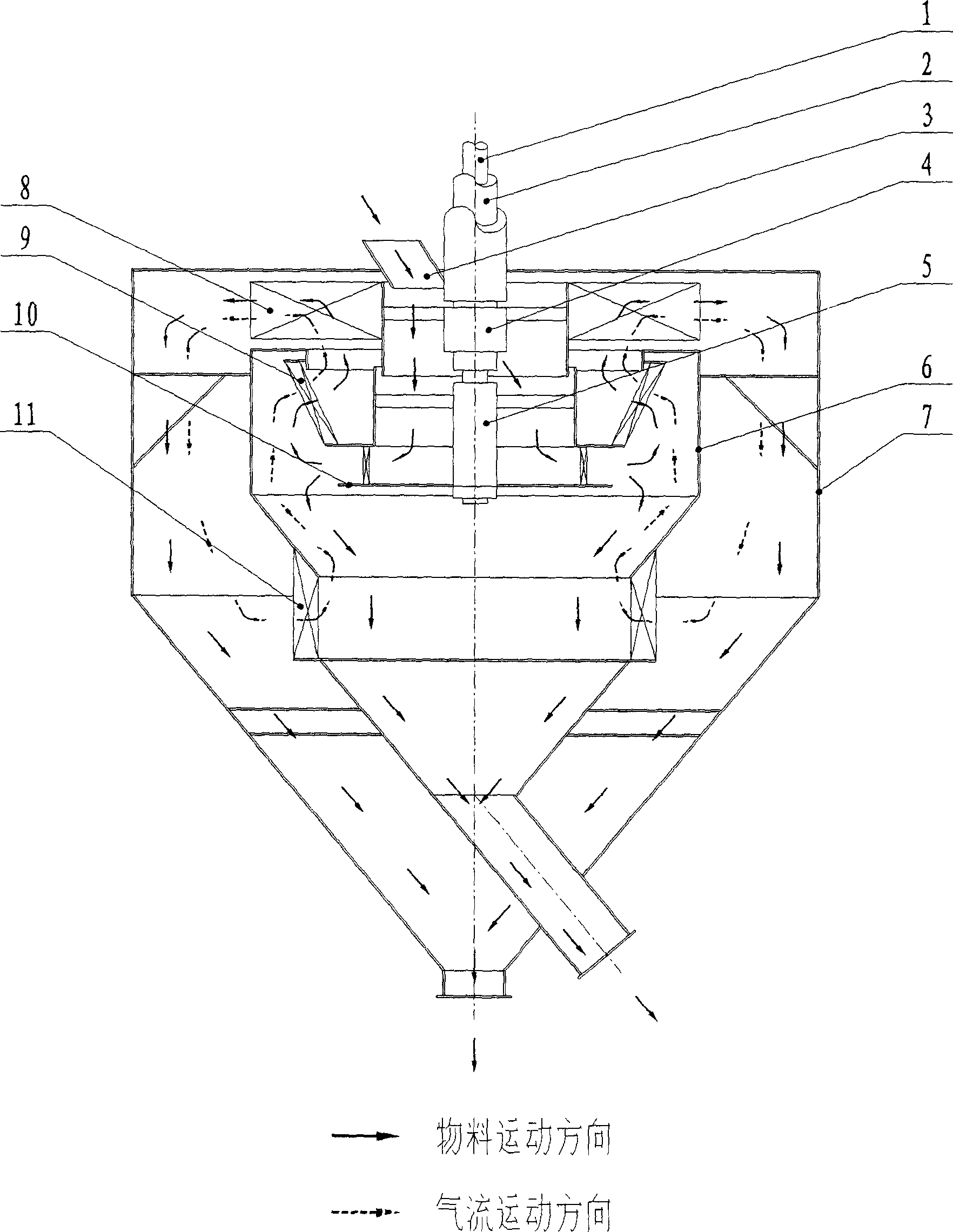
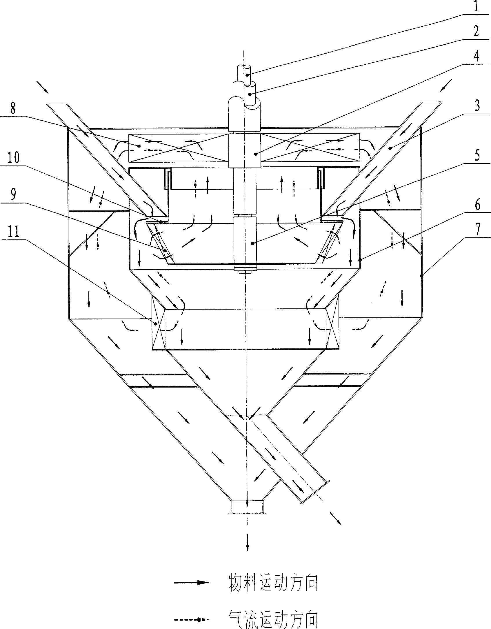
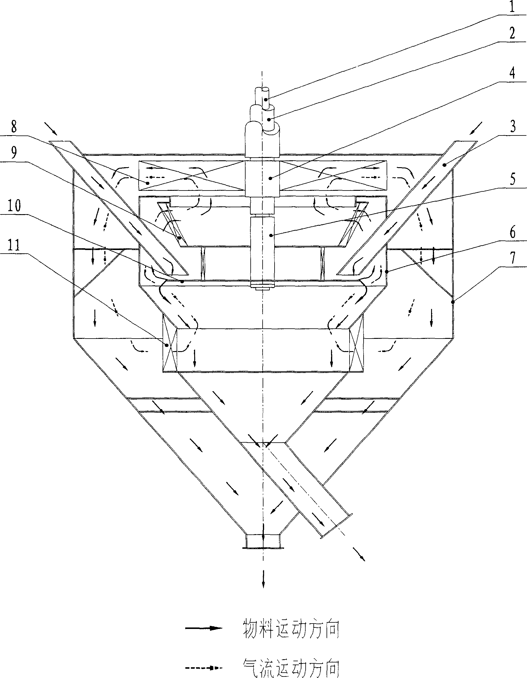
[0010] The first type is called the basic type, the centrifugal wind wheel (4) is installed on the shaft (2), the classification wheel (5) is installed on the shaft (1), the shaft (2) is a hollow shaft, and the shaft (1) passes through the bearing It is sleeved in the shaft (2) to realize differential transmission. The feed inlet is installed near the middle of the powder classifier and feeds the material to the center of the centrifugal wind wheel. This feeding method requires at least one circle of retaining ring on the multi-layer rotating wheel to prevent the material from going inward without the spreader. The outside directly rushes into the wind path and causes rough running. This scheme can also be placed on the bottom of the powder classifier with the transmission system. At this time, the classification wheel (5) needs to be installed on the hollow outer shaft (2),...


PUM


Abstract

A double-wheel different composite powder concentrator consists of nested inner and outer shell, the lower part of inner shell is divided into two sections having guide blades to form ventilation fence way, centrifugal wheel in shell, multi-layer rotary disc composed of classifying wheel and material tray. Centrifugal wheel and classifying wheel are driven by different axle. The material classified through inlet, material spraying tray, classifying wheel, centrifugal wheel, finally settled, to obtain the classified powder.

Description

Technical field [0001] The invention relates to a particle classifying equipment, which is used for coarsely classifying powder material mixtures with different particle sizes, and can be widely used in powder preparation occasions in building materials, chemical industry, metallurgy, mining and other industries, especially suitable for cement industry. Powder selection equipment for raw meal mill and cement mill. Background technique [0002] The prior art can refer to the "air powder separator" in the first section of the third chapter tenth chapter of the trial teaching material "building materials machinery and equipment" published by China Building Industry Press in December, 1980, and China Building Materials Industry Press "Classification equipment in dry production" in Chapter 4 of "Crushing Engineering and Equipment" published in November 1994, and the utility model patent "Differential ring variable air powder separator" with patent number 96215513.6. [0003] The...

Claims


Application Information

Patent Timeline
IPC IPC(8): B07B7/083
Inventor 何正凯
Owner 何正凯
Learn More