Assembling structure of igniter

A technology of igniter and structure, applied in igniter with fuel, combustion ignition, combustion method, etc., can solve problems such as complex design

Inactive Publication Date: 2010-09-29
TOKAI
View PDF3 Cites 0 Cited by
  • Summary
  • Abstract
  • Description
  • Claims
  • Application Information

AI Technical Summary

Problems solved by technology

[0008] Also, if the design is formed to have a plurality of concavities and convexities, the hook portion will also be changed according to

Method used


Image

  • Assembling structure of igniter
  • Assembling structure of igniter
  • Assembling structure of igniter

Examples


no. 1 Embodiment approach

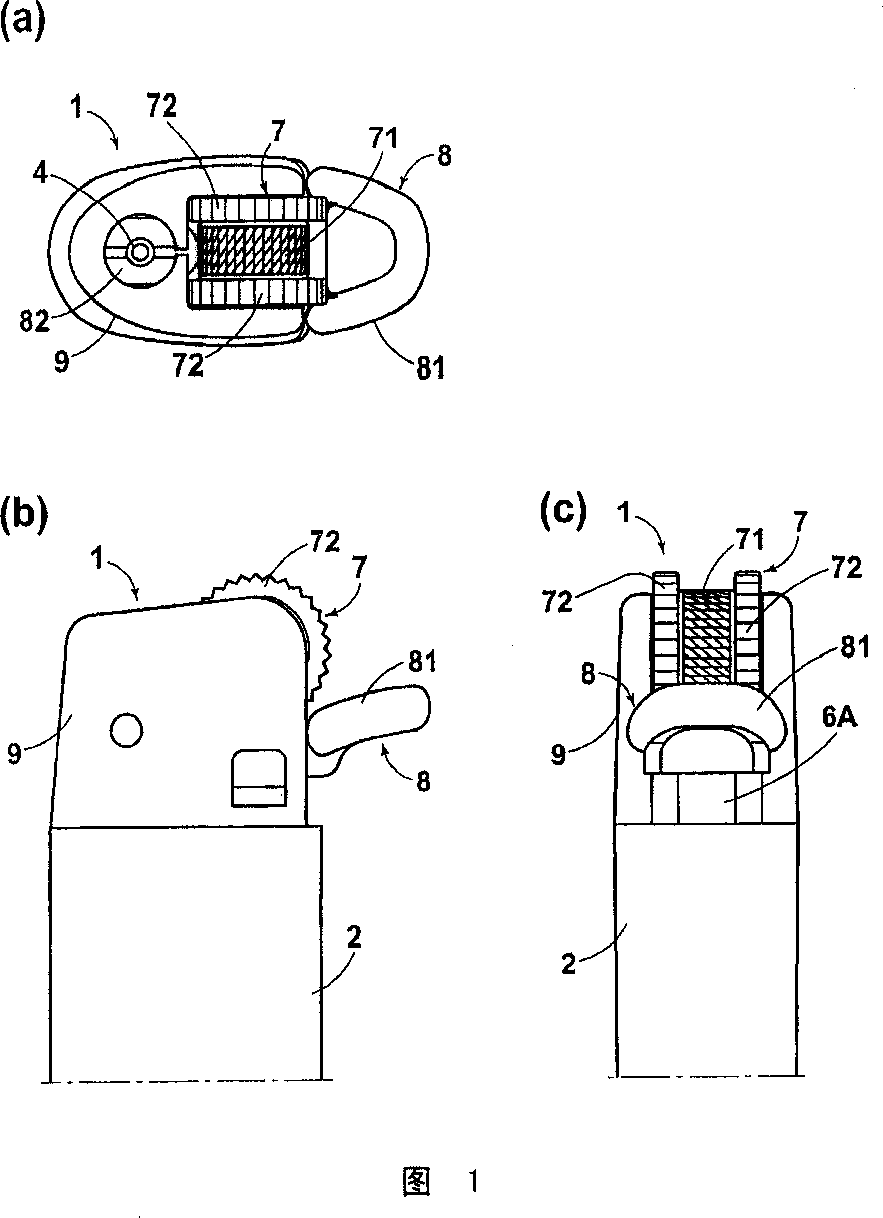
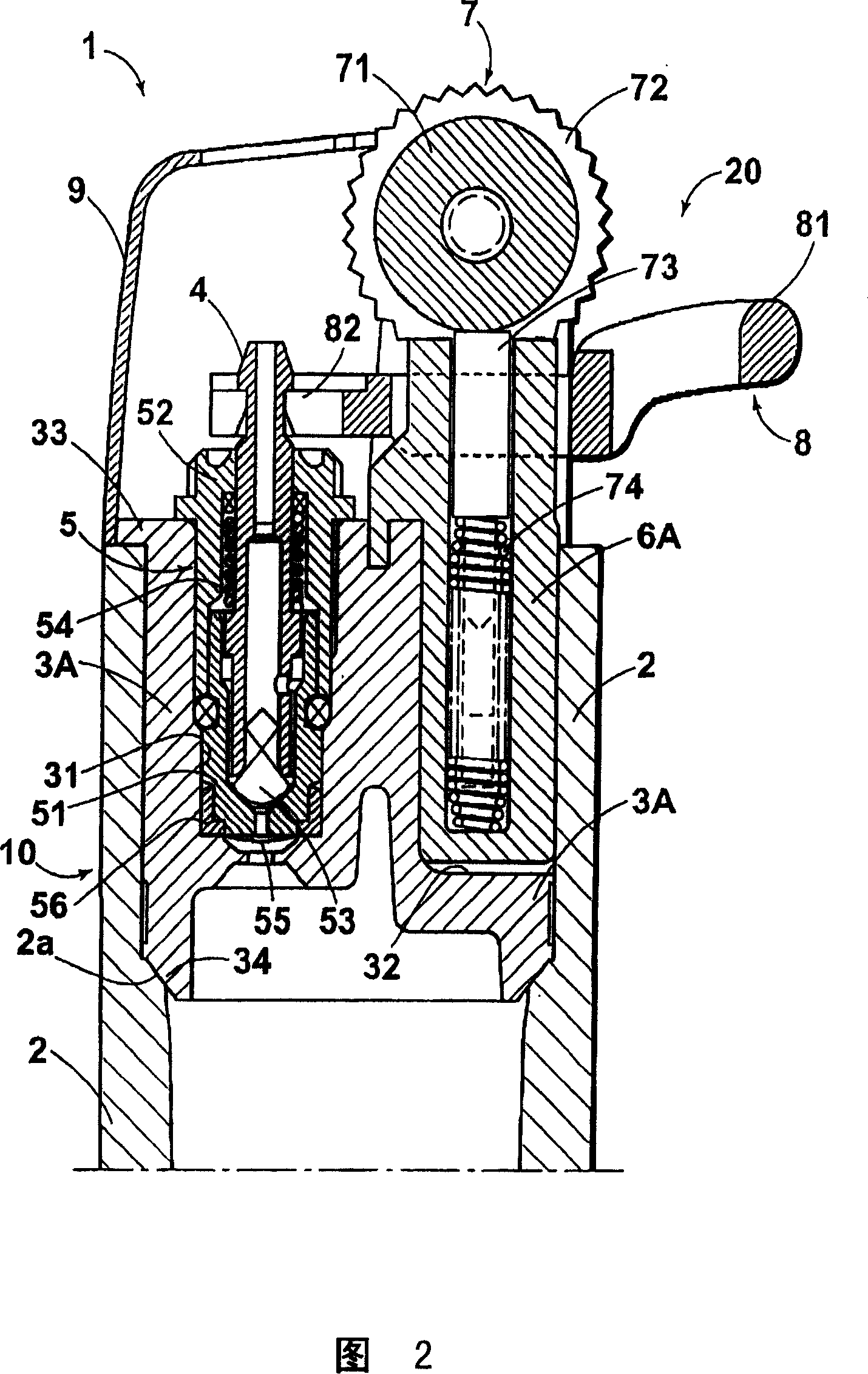
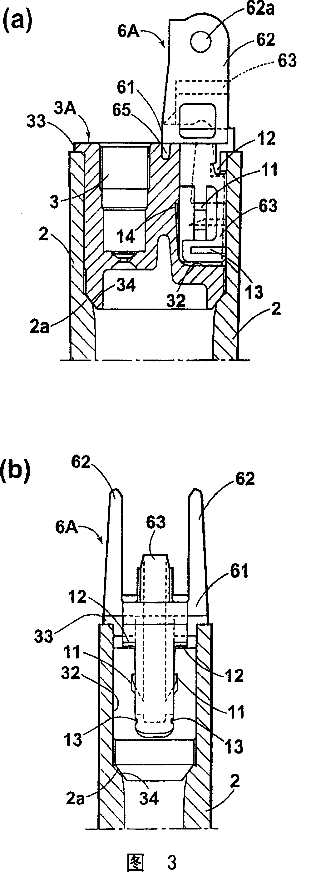
[0045] This embodiment is a flint type igniter, figure 1 It is a top view (a), a side view (b), and a rear view (c) showing the appearance of the igniter. figure 2 It is a central longitudinal sectional side view of the igniter. image 3 It is a partially cutaway side view (a) and a partially cutaway rear view (b) showing the assembled state of the bracket. Figure 4 and Figure 5 is a part diagram, Figure 4 It is the top view (a), central sectional side view (b), rear view (c) of the upper cover of the box, Figure 5 It is a top view (a), a central sectional side view (b), a side view (c), a rear view (d), a sectional rear view (e), and a bottom view (f) of the bracket. In addition, in the following description, based on how the igniter is used, the figure 1 In (b), the left side is referred to as the front, and the right side is referred to as the rear.

[0046] Such as figure 2 As shown, the igniter 1 is formed by assembling a lower assembly body 10 and an upper a...

no. 2 Embodiment approach

[0070] This embodiment is also a flint type igniter, Image 6 It is a partially cutaway side view (a) and a partially cutaway rear view (b) showing the assembled state of the bracket. Figure 7 and Figure 8 is a part diagram, Figure 7 It is the top view (a), central sectional side view (b), rear view (c) of the upper cover of the box, Figure 8 It is a top view (a), a central sectional side view (b), a side view (c), a rear view (d), a sectional rear view (e), and a bottom view (f) of the bracket. The basic structure of the igniter 1 of flint formula and figure 1 The igniter is the same, and although the structure of the assembly hook of the box top cover 3B and the bracket 6B is different, the same reference numerals are assigned to the common parts, and the description thereof will be omitted.

[0071] The assembly and fixing structure of the box upper cover 3B and the bracket 6B of the present embodiment is as follows: Image 6 As shown, it is composed of the 5th and...

no. 3 Embodiment approach

[0077] This embodiment is also a flint type igniter, Figure 9 It is a partially cutaway side view (a) and a partially cutaway rear view (b) showing the assembled state of the bracket. Figure 10 and Figure 11 is a part diagram, Figure 10 It is the top view of the box cover (a), the central sectional side view (b), and the sectional rear view of the bracket assembly hole (c), Figure 11 It is a top view (a), a central sectional side view (b), a side view (c), a rear view (d), a sectional rear view (e), and a bottom view (f) of the bracket. The basic structure of the igniter 1 of flint formula and figure 1 The igniter is the same, and although the assembly hook structure of the case upper cover 3C and the bracket 6C is different, the same reference numerals are assigned to the common parts as described above, and the description thereof will be omitted.

[0078] The assembly and fixing structure of the case upper cover 3C and the bracket 6C of the present embodiment is as...


PUM


Abstract

The invention is aimed to provide an assembly structure of a lighter, in which a lower assembly and an upper assembly are assembled so that a joint part therebetween does not appear on a side wall surface. In an assembly structure of a lighter formed by preparing a lower assembly 10 formed by mounting a jet nozzle 4, a valve mechanism 5 and the like onto a tank upper lid 3A and an upper assembly 20 formed by mounting an ignition mechanism 7, a gas lever 8 and the like onto a bracket 6A, assembling the upper and lower assemblies, and attaching a cap 9 to the resultant assembly, a lower part ofthe bracket 6A in the upper assembly 10 is inserted into the tank upper lid 3A in the lower assembly 10, and they are then assembled and fixed inside the insertion part by hook engagements 11 to 14 or welding. The assembly structure is configured so that the upper part of the bracket 6A is covered by attachment of the cap 9 so that the bracket 6A is not exposed to a side wall surface of the lighter.

Description

technical field [0001] The present invention relates to an assembly structure of an igniter. In an igniter that ignites gas ejected from a nozzle by a flint-type or discharge-type ignition mechanism, the main body of the tank that stores fuel and adjusts the amount of gas ejection is assembled and assembled. Fix the ignition operating mechanism that ignites the ejected gas. Background technique [0002] In general, an igniter (gas igniter) is composed of the following parts: a tank body that stores fuel gas; a nozzle that ejects gas from an outlet at the front end; a valve mechanism that opens and closes the ejection of gas; A gas lever that operates to open the valve mechanism during operation; an ignition mechanism that ignites the ejected gas in accordance with the ignition operation; a cover. The assembly process is as follows: prepare the lower assembly and the upper assembly and finally assemble the two together, wherein the lower assembly is assembled with nozzles an...

Claims


Application Information

Patent Timeline
IPC IPC(8): F23Q2/16F23Q2/28F23Q2/34F23Q2/50
Inventor 铃木孝之望月哲也佐藤诚
Owner TOKAI
Why Eureka
Try Eureka