Mask frame assembly for depositing a thin layer of an electroluminescent device and method for depositing a thin layer

A technology of mask components and mask frames, which is applied in electroluminescent light sources, electric solid-state devices, semiconductor devices, etc., and can solve problems such as different colors, increased production costs, and increased number of masks

Active Publication Date: 2005-04-20
SAMSUNG DISPLAY CO LTD
View PDF1 Cites 48 Cited by
  • Summary
  • Abstract
  • Description
  • Claims
  • Application Information

AI Technical Summary

Problems solved by technology

This not only increases the production cost, but also prolongs the production cycle
Also, even if the icon patterns 14 are the same, but their colors are different, the number of masks corresponding to these colors has to be increased, which will cause the same problem as above

Method used


Image

  • Mask frame assembly for depositing a thin layer of an electroluminescent device and method for depositing a thin layer
  • Mask frame assembly for depositing a thin layer of an electroluminescent device and method for depositing a thin layer
  • Mask frame assembly for depositing a thin layer of an electroluminescent device and method for depositing a thin layer

Examples


Embodiment Construction

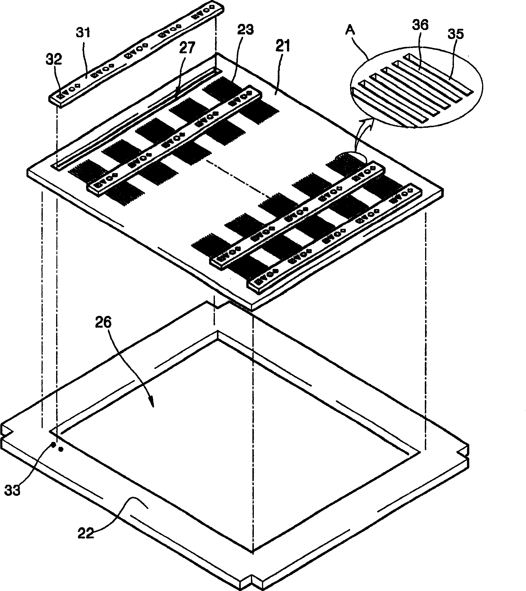
[0024] Such as figure 2 As shown, the mask frame assembly of the present invention can include a main mask 21, which is formed with a pattern 23 corresponding to each required unit cell; icon masks 31, which are respectively arranged on the main mask 21 and a mask frame 22 formed with openings 26 corresponding to the main mask 21 . As shown, mask frame 22 may be attached to mask 21 and icon mask 31 .

[0025] The main mask 21 may be formed with a large number of patterns 23 and a large number of openings 27 . Each pattern 23 may be formed as a unitary body. As can be seen from the enlarged view of the pattern 23 shown as "A", the pattern 23 may include a large number of parallel slits 35, all of which may be formed by perforating (or patterning) the master mask 21, and as a result, A number of strips 36 are also formed between the slits 35 . Organic substances can be deposited through the slits 35 on a substrate (not shown) disposed under the master mask 21 . Master mask...


PUM


Abstract

The present invention discloses a mask frame assembly for depositing thin layers of organic electroluminescent devices. The mask frame assembly includes the following parts: a main mask, which is formed with patterns corresponding to a large number of unit cells; an icon mask (with icon patterns), which is arranged on the main mask and corresponds to the main mask. one or more openings of the mask; and a mask frame formed with openings corresponding to the main mask and connected to the main mask and the icon mask.

Description

technical field [0001] The invention relates to a mask frame assembly for depositing a thin layer of an organic electroluminescent device. In particular, the present invention relates to a mask frame assembly, which respectively includes a master mask formed with a pattern corresponding to a unit cell, and an icon mask having an icon pattern. The invention also relates to methods of depositing thin layers using the assembly. Background technique [0002] An electroluminescent device is an efficient optical device, which has many advantages, such as: fast response speed, wide viewing angle, and high-quality contrast ratio. Electroluminescent devices include organic electroluminescent devices and inorganic electroluminescent devices. The difference is based on the type of substance (organic or inorganic) forming the electroluminescent layer. Compared with inorganic electroluminescent devices, organic electroluminescent devices have higher definition and faster response spee...

Claims


Application Information

Patent Timeline
Patent Type & Authority Applications(China)
IPC IPC(8): H05B33/10C23C14/04C23C14/12C23C14/50C23C16/00H01L51/50H05B33/14
CPCC23C14/042C23C14/12H10K71/166H05B33/10
Inventor 金鲜喜
Owner SAMSUNG DISPLAY CO LTD
Why Eureka
Try Eureka