Electromagnetic absorber using resistive material

a resistive material and absorber technology, applied in the direction of instruments, tickets, instruments, etc., can solve the problems of complex manufacturing process, salisbury screen, high difficulty in adjusting absorption frequency band and absorption characteristics,

Active Publication Date: 2012-04-24
ELECTRONICS & TELECOMM RES INST
View PDF34 Cites 16 Cited by
  • Summary
  • Abstract
  • Description
  • Claims
  • Application Information

AI Technical Summary

Problems solved by technology

Since such an electromagnetic absorber is generally developed after much trial and error, it is disadvantageous in that the manufacturing process thereof is complicated and it is highly difficult to adjust an absorption frequency band and absorption characteristics.
However, such a Salisbury screen is disadvantageous in that the thickness of the dielectric spacer from the metal conductive ground plane must be more than at least λ / 4.

Method used


Image

  • Electromagnetic absorber using resistive material
  • Electromagnetic absorber using resistive material
  • Electromagnetic absorber using resistive material

Examples


Embodiment Construction

[0025]Hereinafter, exemplary embodiments of the present invention will be described in detail with reference to the accompanying drawings.

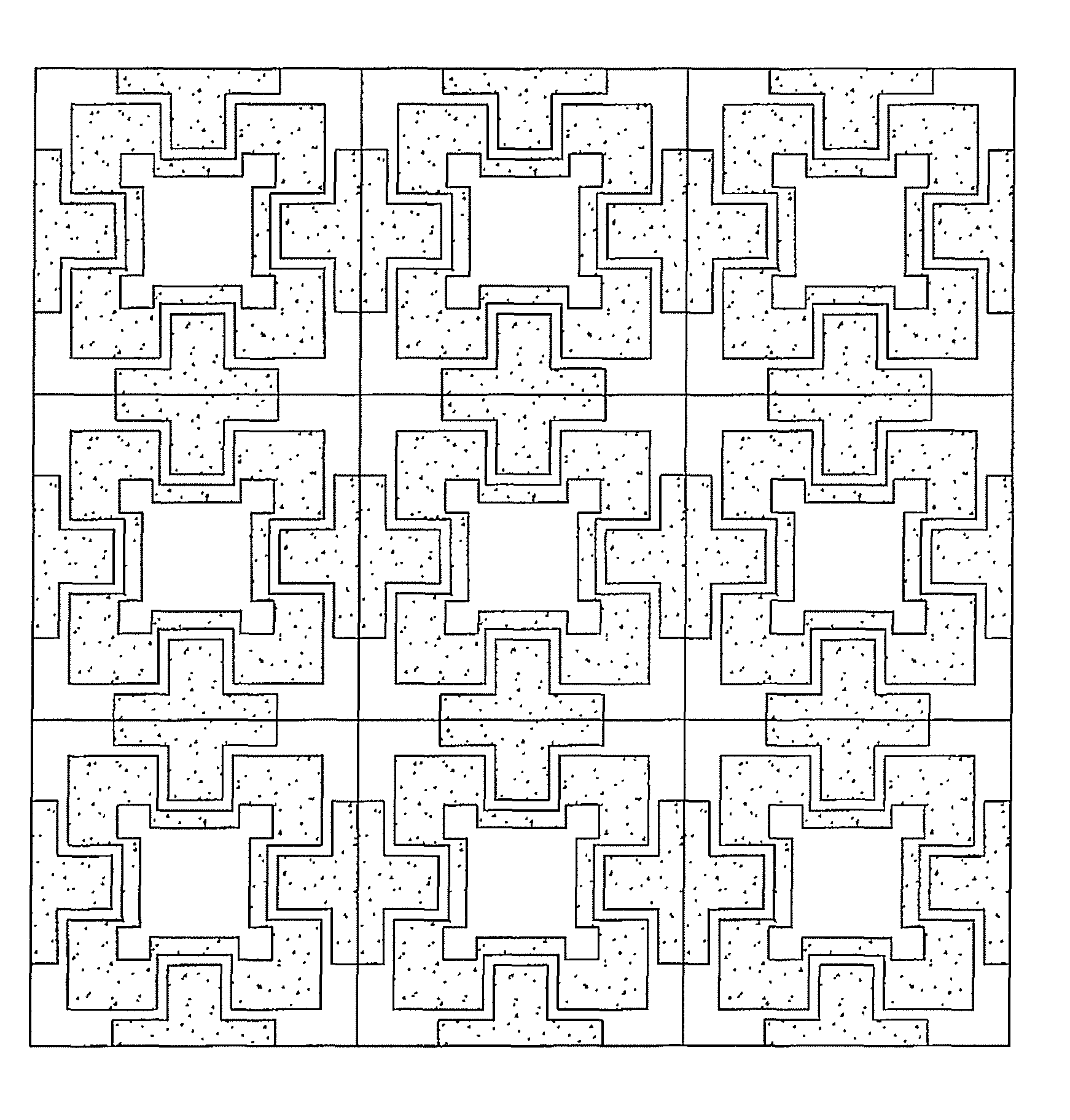
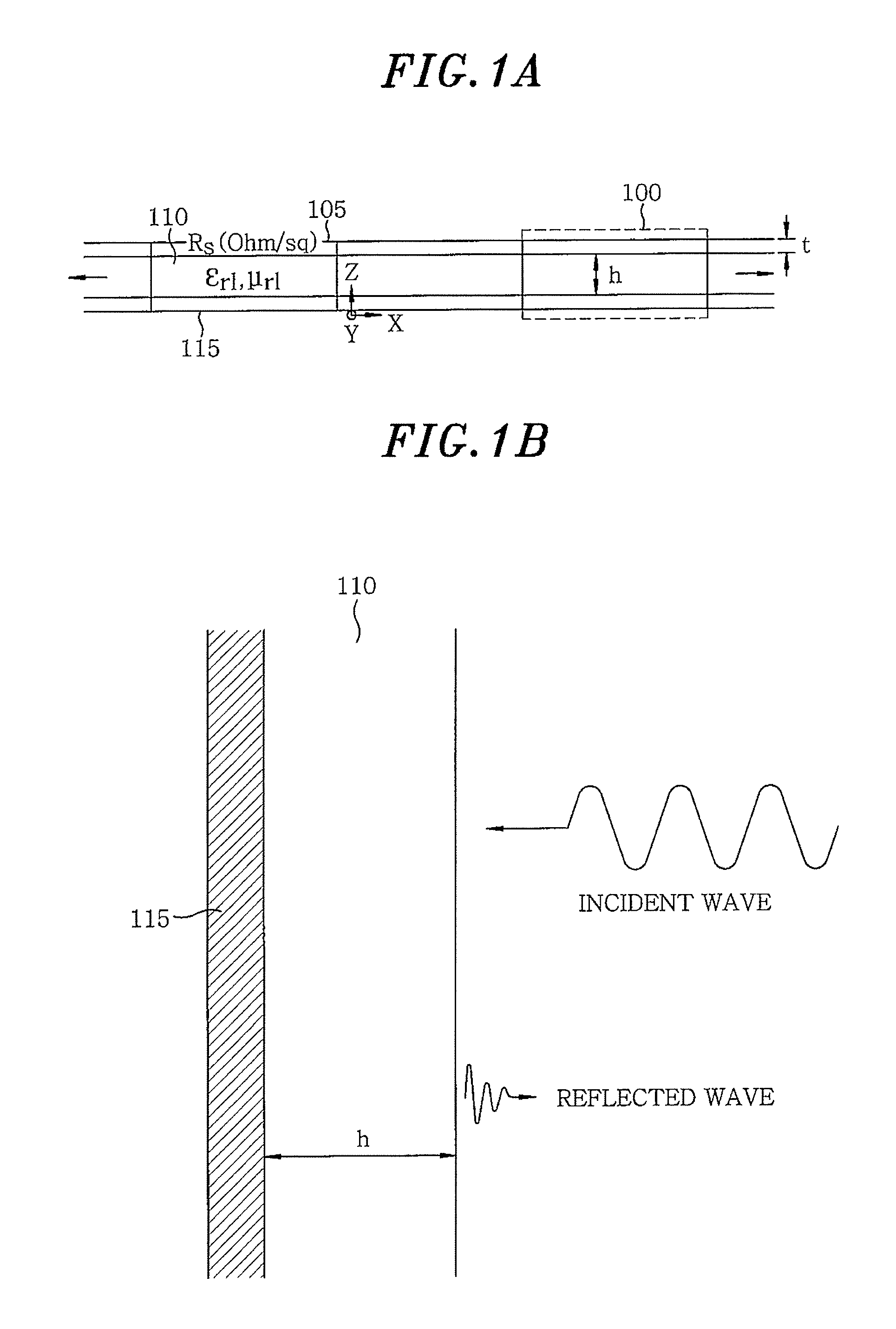
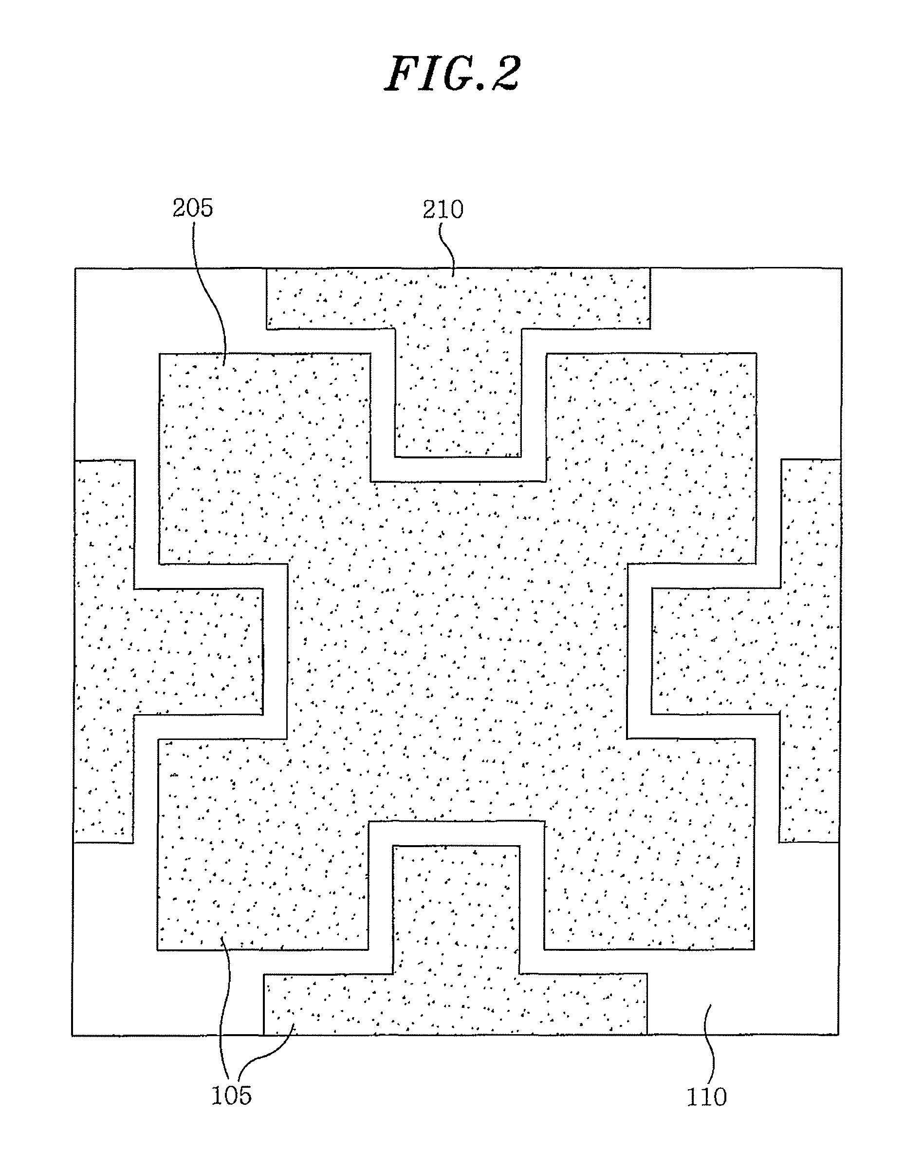
[0026]FIGS. 1A and 1B are front views of an electromagnetic absorber using a resistive material in accordance with an embodiment of the present invention. Referring to FIGS. 1A and 1B, the electromagnetic absorber is made by periodically arranging unit cells 100 for a resistive electromagnetic bandgap. Each of the unit cells 100 includes a metal conductive ground plane 115, a dielectric layer 110 formed on the metal conductive ground plane 115, and a unit cell pattern 105 made of a resistive material formed on the dielectric layer 110.

[0027]Both the dielectric layer 110 and the unit cell pattern 105 have a structure of incorporating loss into a frequency selective surface (FSS) typically composed of a dielectric material and a unit cell pattern made of a metal conductor. With such structure, the dielectric layer 110 and the unit cell pattern 105 m...


PUM


Abstract

An electromagnetic absorber using resistive material includes a ground plane of a conductive material; a dielectric layer formed on the ground plane; and a pattern layer in which specific unit cell patterns made of a resistive material are periodically arranged on the dielectric layer. The electromagnetic absorber is applied to an electronic toll collection system, a transportation device, a building structure, an electronic device and an anechoic chamber.

Description

CROSS-REFERENCE(S) TO RELATED APPLICATION(S)[0001]The present invention claims priority of Korean Patent Application No. 10-2008-0130776, filed on Dec. 22, 2008, which is incorporated herein by reference.FIELD OF THE INVENTION[0002]The present invention relates to an electromagnetic absorber; and, more particularly, to an electromagnetic absorber which is capable of partially reflecting and transmitting electromagnetic waves in various applications.BACKGROUND OF THE INVENTION[0003]An electromagnetic bandgap (EBG) may be implemented by periodically arranging specifically designed unit cell patterns on a typical electric conductor at regular intervals. Since a tangential component of a magnetic field on the surface of the electromagnetic bandgap becomes zero, the electromagnetic bandgap has the characteristic of preventing current from flowing through the surface. Such an electromagnetic bandgap may be regarded as a magnetic conductor opposite to an electric conductor. The surface of ...

Claims


Application Information

Patent Timeline
Patent Type & Authority Patents(United States)
IPC IPC(8): H01Q17/00
CPCH01Q17/008G07B15/063
Inventor SIM, DONG-UKKWON, JONG HWAKWAK, SANG ILYUN, JE HOONKIM, CHANG-JOO
Owner ELECTRONICS & TELECOMM RES INST
Why Eureka
Try Eureka