Method and system for logic design for cell projection particle beam lithography

a particle beam lithography and logic design technology, applied in the field of particle beam lithography, can solve the problems of low throughput, high cost of masks, and rapid growth, and achieve the effects of optimizing or minimizing or reducing the writing tim

Inactive Publication Date: 2009-08-25
D2S
View PDF8 Cites 19 Cited by
  • Summary
  • Abstract
  • Description
  • Claims
  • Application Information

AI Technical Summary

Problems solved by technology

However, mask cost, which is rapidly growing with shrinking feature size, is becoming a serious problem for semiconductor manufacturing.
However, the problem with this approach has been its relatively low throughput, which has hindered its use for volume production.
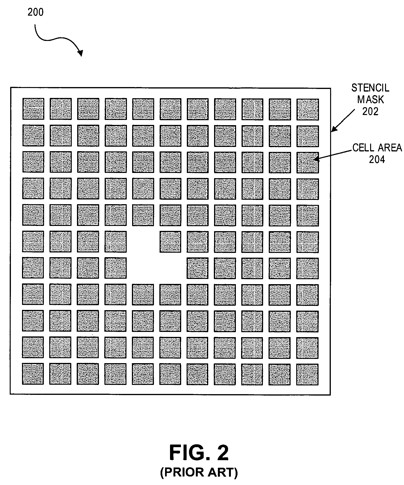
However, the problem of CP is the limitation of the number of cells that can be contained in one stencil mask.
The limited number of cells on the stencil results in the case that only a part of the cells used in the integrated circuit or chip can be drawn with CP, which results in a limited throughput improvement.
However, due to stencil capacity limitation, a substantial number of cells cannot be included in the stencil, forcing the patterns for these cells to be drawn by VSB shots.
Thus, the writing time reduction by CP is limited.

Method used


Image

  • Method and system for logic design for cell projection particle beam lithography
  • Method and system for logic design for cell projection particle beam lithography
  • Method and system for logic design for cell projection particle beam lithography

Examples


Embodiment Construction

[0035]Various embodiments of the invention are described herein with reference to the drawings. It should be noted that the drawings are not drawn to scale and that elements of similar structures or functions are represented by like reference numerals throughout the drawings.

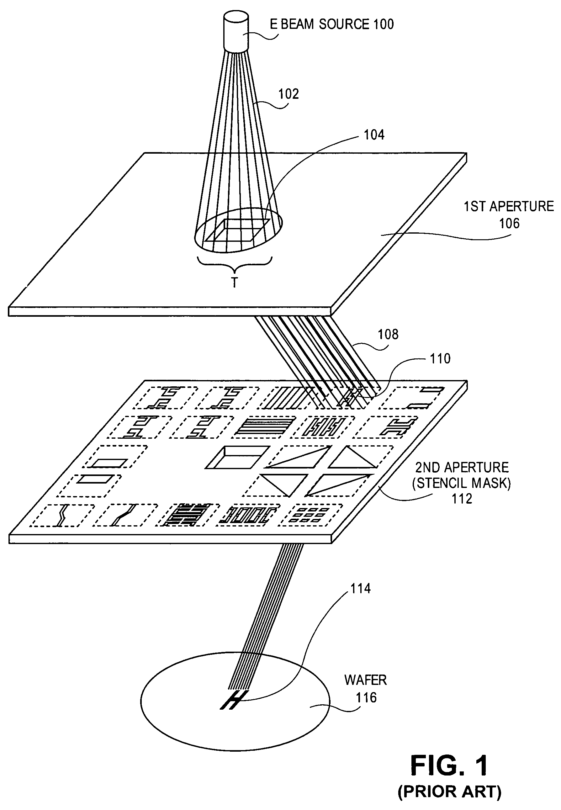
[0036]The following discussion mainly describes electron beam (EB) direct writing (EBDW) as an application of particle beam lithography. This invention should not be limited to only EB direct writing (EBDW), however. This invention can be applied in a similar manner to mask writing using an electron beam (EB) writer with cell projection (CP) capability, resulting in an improved throughput.

[0037]Accordingly, it should be appreciated that this invention may also be applied to other drawing technologies which transcribe patterns using at least two apertures (stencil masks) and using types of particle beams other than an electron beam (EB), such as an optical (light) laser beam, an X-ray beam or any other particle b...


PUM


Abstract

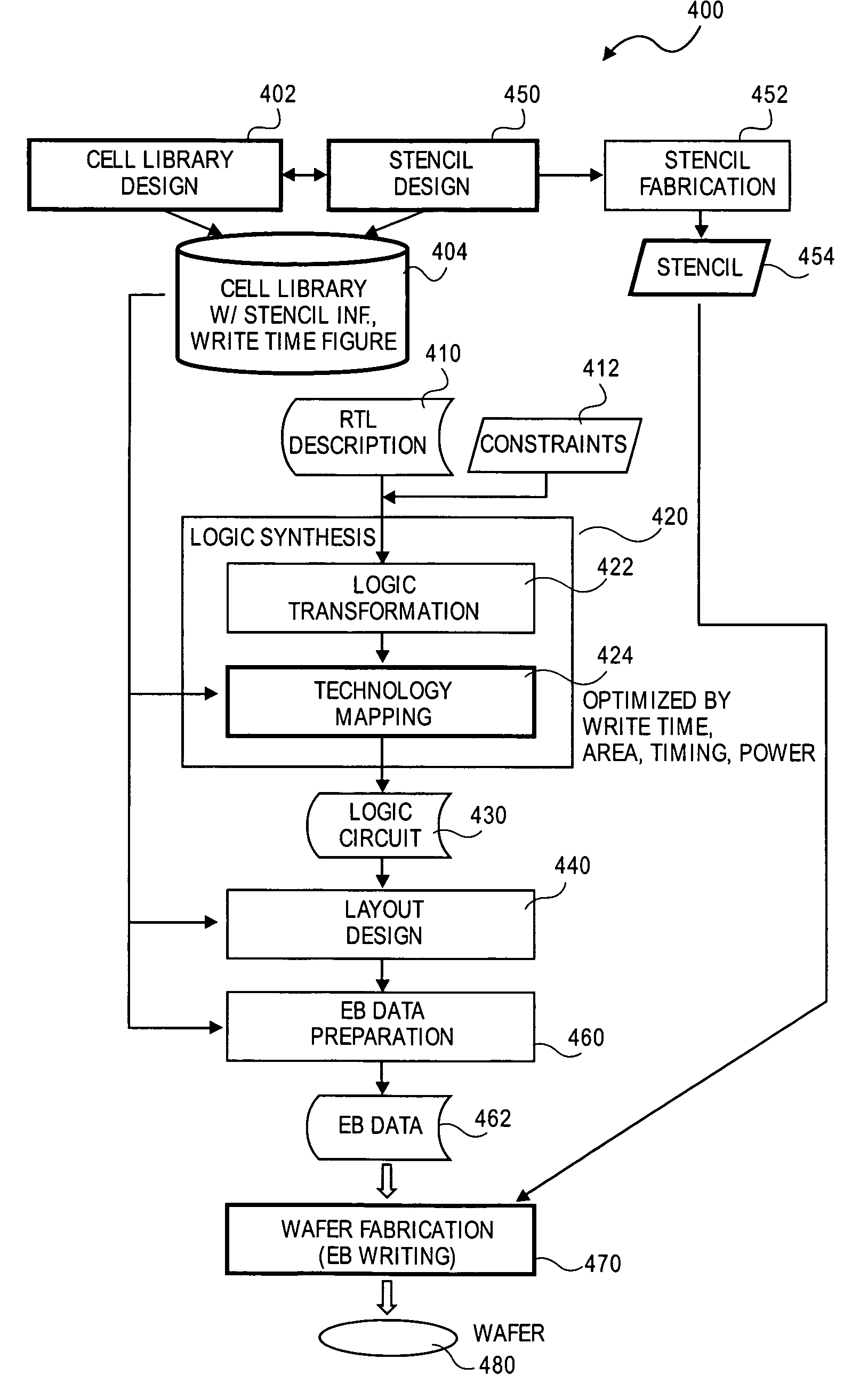
A method for particle beam lithography, such as electron beam (EB) lithography, includes predefining a stencil design having a plurality of cell patterns with information from a cell library, fabricating the stencil design, synthesizing a functional description into a logic circuit design after predefining the stencil design so that one or more characteristics of the stencil design are considered during synthesizing of the functional description into the logic circuit design, optimizing the logic circuit design, generating a layout design from the optimized logic circuit design, and forming the logic circuit on a substrate according to the stencil design and the layout design.

Description

BACKGROUND[0001]1. Field[0002]The field of the present invention relates to particle beam lithography and, in particular, to logic design for cell projection particle beam lithography.[0003]2. Description of Related Art[0004]In today's semiconductor manufacturing process, optical lithography using photomasks is commonly used. However, mask cost, which is rapidly growing with shrinking feature size, is becoming a serious problem for semiconductor manufacturing. To solve this issue, various approaches that do not use a photomask, such as maskless lithography, have been proposed. One of the promising maskless lithography approaches is electron beam (EB) direct writing (EBDW). However, the problem with this approach has been its relatively low throughput, which has hindered its use for volume production. Thus, EBDW has been applied only for research and for interconnect layers of production application-specific integrated circuits (ASICs).[0005]To reduce EB writing time, a cell projecti...

Claims


Application Information

Patent Timeline
Patent Type & Authority Patents(United States)
IPC IPC(8): G21K5/04G06F17/50
CPCB82Y10/00H01J37/3174G03F1/20B82Y40/00
Inventor YOSHIDA, KENJIMITSUHASHI, TAKASHIMATSUSHITA, SHOHEIFUJIMURA, AKIRA
Owner D2S
Why Eureka
Try Eureka