
Projector

A technology for projectors and projection optical systems, which is applied in the field of projectors, and can solve the problems of increased sound from the strip fan used for exhaust and the inability to ensure the quietness of the projector, so as to achieve the effect of ensuring quietness and preventing swinging

Inactive Publication Date: 2005-04-27
SEIKO EPSON CORP
View PDF2 Cites 3 Cited by
  • Summary
  • Abstract
  • Description
  • Claims
  • Application Information

AI Technical Summary

Problems solved by technology

[0009] Therefore, it is difficult to efficiently inhale the air inside the projector by the strip fan for exhaust, and the sound of the strip fan itself for exhaust is loud, and the quietness of the projector cannot be ensured.

Method used


Image

  • Projector
  • Projector
  • Projector

Examples


Embodiment Construction

[0039] Next, one embodiment of the present invention will be described based on the drawings.

[0040] (1. The main components of the projector)

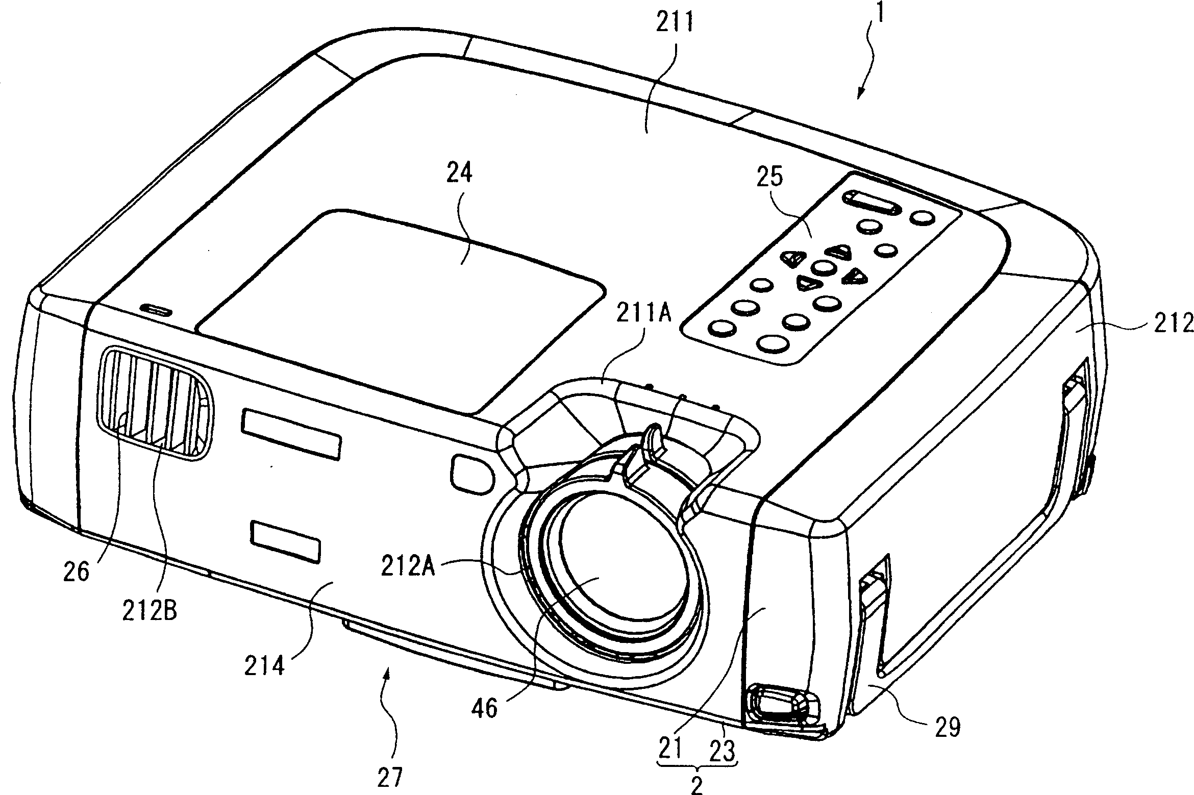
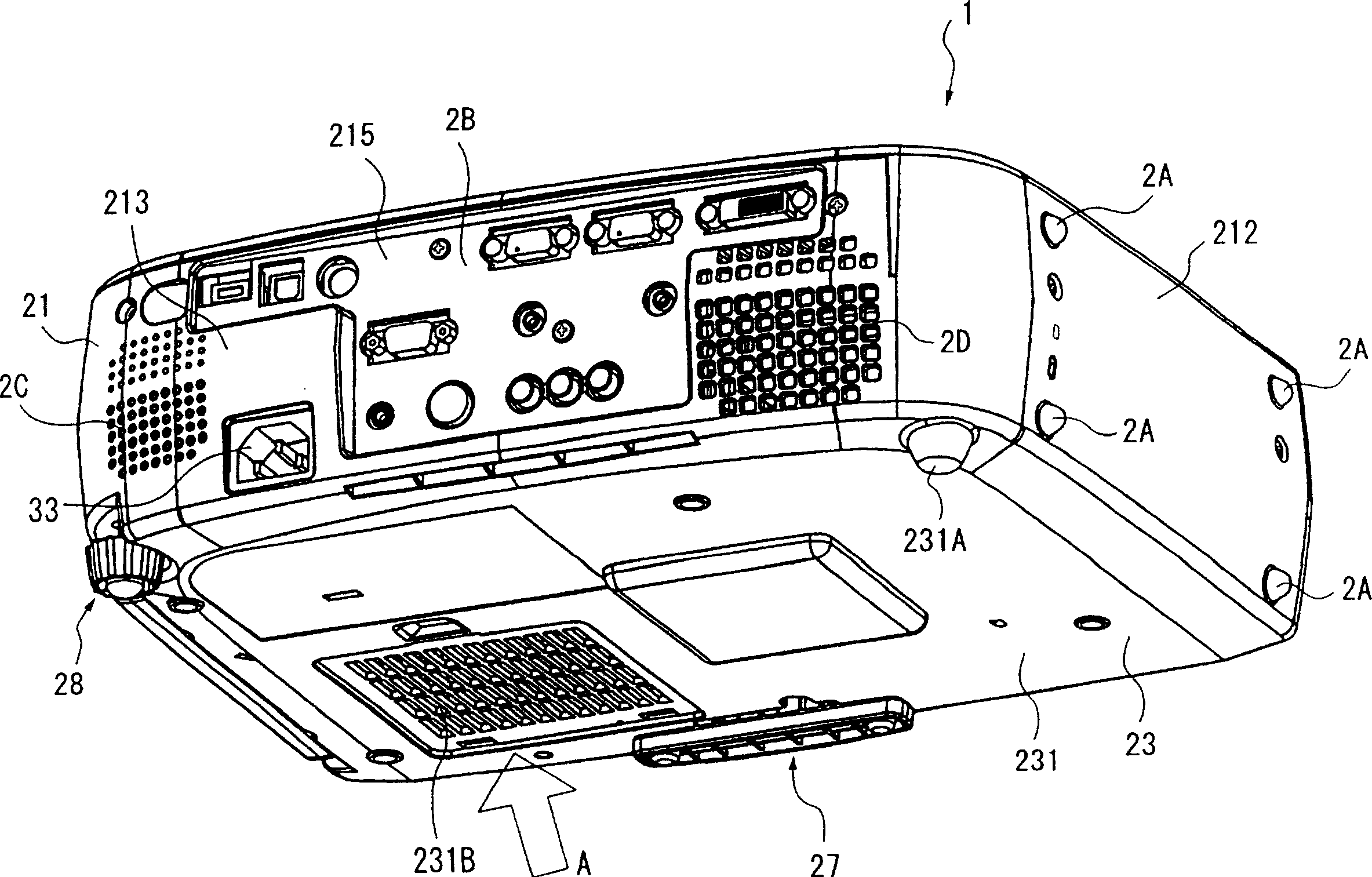
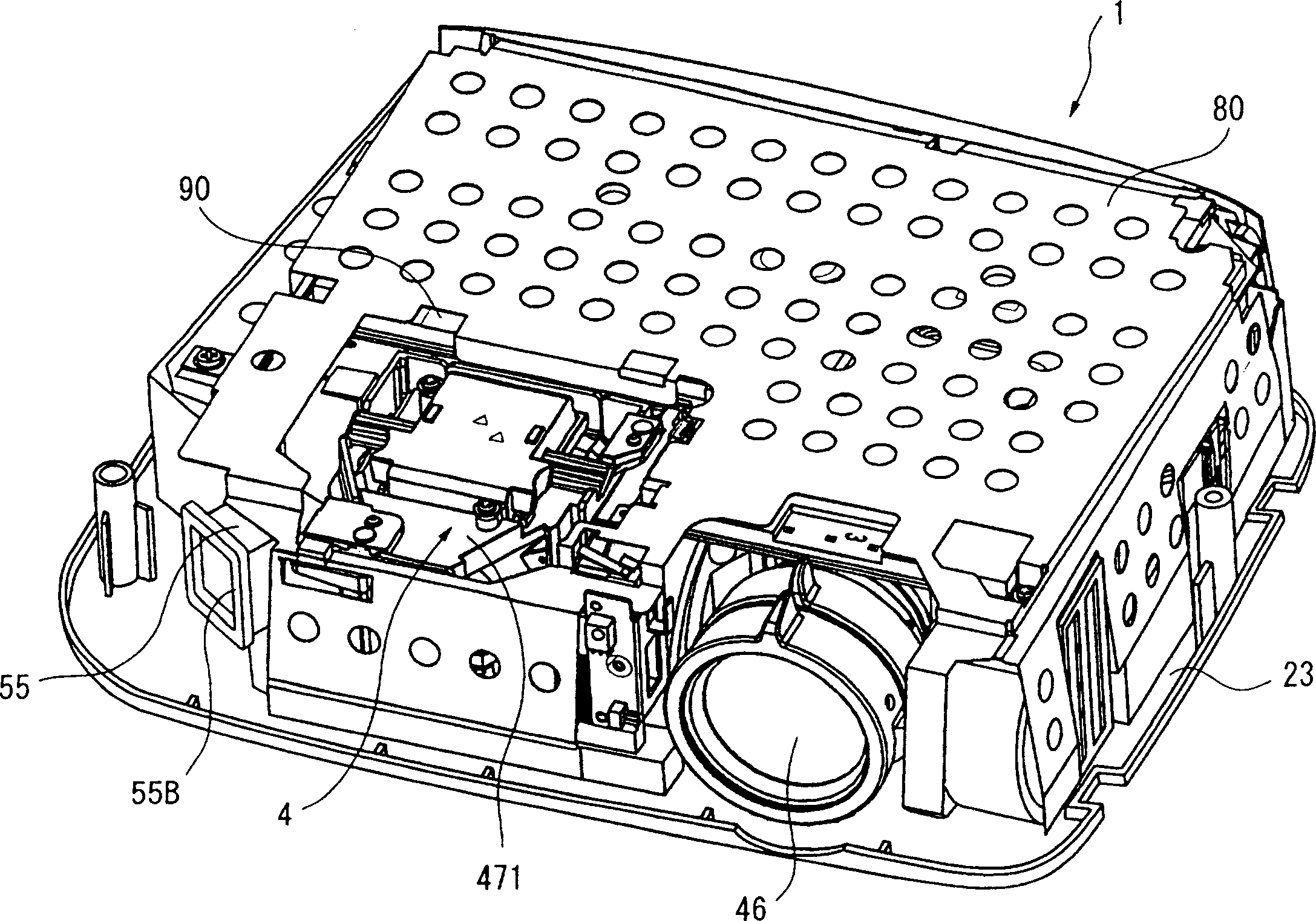
[0041] figure 1 is an overall perspective view of the projector 1 according to the present embodiment seen from above, figure 2 is an overall perspective view of projector 1 viewed from below, Figure 3 to Figure 5 It is a perspective view showing the inside of the projector 1 . Specifically image 3 From figure 1 The state where the upper case 21 of the projector 1 is removed. Figure 4 From image 3 The figure seen from the rear side with the shield plate 80 and the driver board 90 removed. Figure 5 From Figure 4 The state where the optical unit 4 is removed. Furthermore, these parts 4, 21, 55, 80, 90 constituting the projector will be described in detail below.

[0042] exist Figure 1 to Figure 5 Among them, the projector 1 has an outer casing 2, a power supply unit 3 accommodated in the outer casing 2, a planar U-...


PUM


Abstract

A projector, wherein a discharge sirocco fan (55) for discharging air inside the projector to the outside is disposed so that the suction port (55A) thereof is positioned along a surface orthogonal to a light path surface formed of an optical unit (4), i.e., along the thickness direction of the projector, whereby since the optical unit (4) and the discharge sirocco fan (55) must not be disposed overlappingly with each other in the thickness direction of the projector, an exhaust efficiency can be increased and a silentness can be assured by efficiently sucking air inside the projector.

Description

technical field [0001] The present invention relates to projectors. Background technique [0002] Historically, it has been known to use projectors for presentations at conferences, societies, exhibitions, and the like. In such a projector, an optical image is formed by modulating a light beam emitted from a light source device by a light modulation device according to image information, and the optical image is enlarged and projected by a projection optical system. [0003] In such a projector, it is necessary to increase the brightness of the light source in order to clearly display the projected optical image, and accordingly, it is necessary to discharge the heat generated by the light source to the outside. [0004] For this reason, projectors employ an exhaust structure in which air heated inside is exhausted to the outside by a fan (see, for example, Patent Document (JP-A-11-354963)). [0005] In this exhaust structure, as the fan that exhausts the air inside the pr...

Claims


Application Information

Patent Timeline
Patent Type & Authority Applications(China)
IPC IPC(8): G03B21/00G03B21/16H04N5/74H04N9/31
CPCH04N9/3144H04N9/3141H04N9/3197H04N9/3105G03B21/00G03B21/16G03B21/005
Inventor 伊藤信介松宫俊夫
Owner SEIKO EPSON CORP
Learn More