Back light system and its manufacturing method

A technology of a backlight system and a manufacturing method, which is applied in the field of backlight systems, can solve the problems of low light output brightness, high cost, complex structure, etc., and achieve the effects of improved light output brightness, reduced cost, and simple structure

Inactive Publication Date: 2005-05-04
HONG FU JIN PRECISION IND (SHENZHEN) CO LTD +1
View PDF5 Cites 6 Cited by
  • Summary
  • Abstract
  • Description
  • Claims
  • Application Information

AI Technical Summary

Problems solved by technology

[0006] In order to overcome the defects of low light output brightness, complex structure and high cost of the backlight system panel

Method used


Image

  • Back light system and its manufacturing method
  • Back light system and its manufacturing method
  • Back light system and its manufacturing method

Examples


Example Embodiment

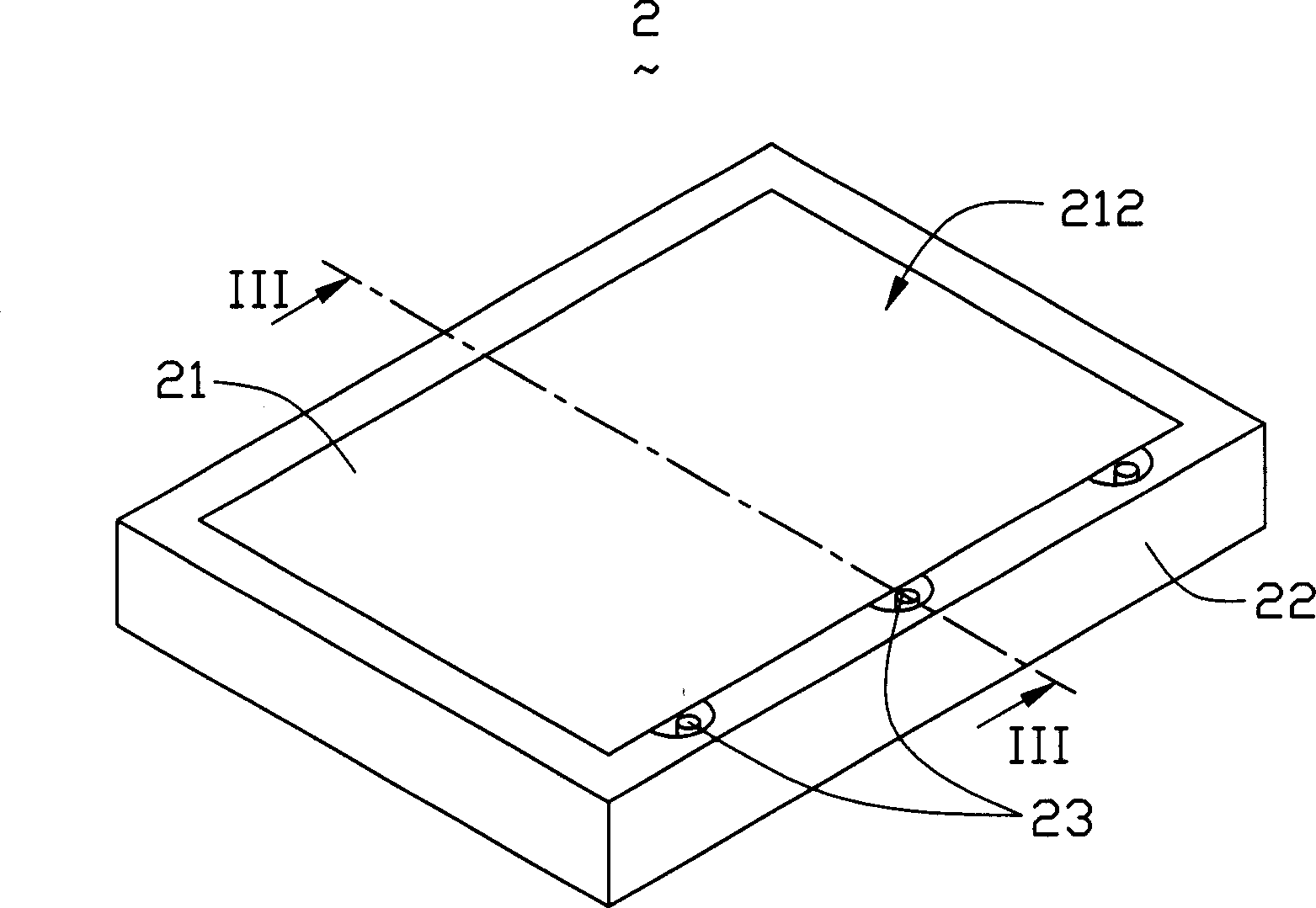
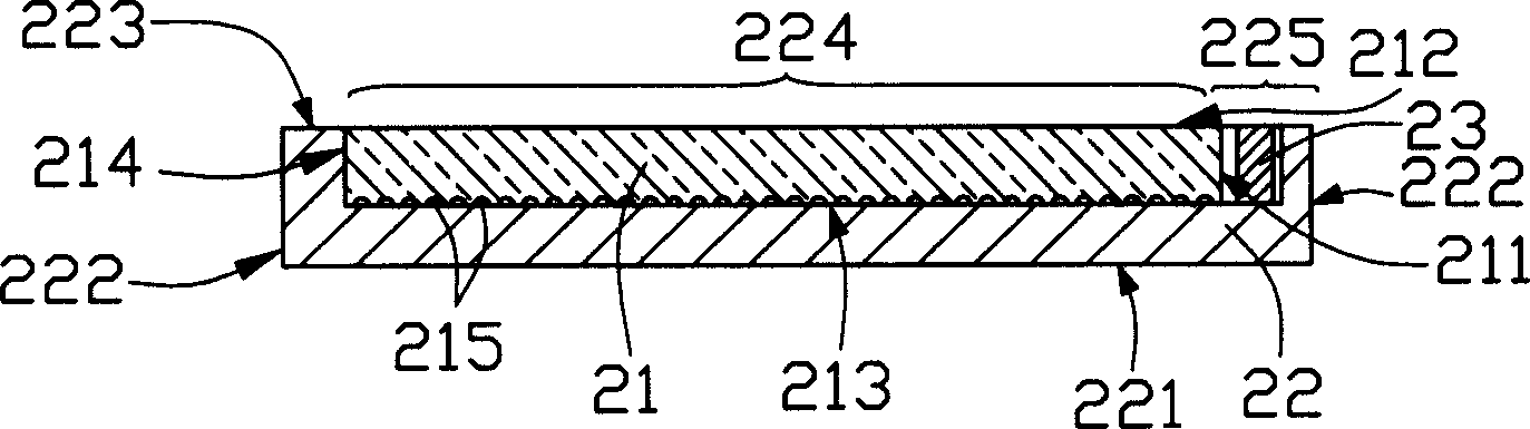
[0015] Please refer to figure 2 and image 3 , Is a schematic diagram of the structure of the backlight system 2 of the present invention. The backlight system 2 includes a light guide plate 21, a frame body 22 and a plurality of light sources 23. The frame 22 is box-shaped and includes a lower surface 221, a plurality of side surfaces 222 intersecting the lower surface 221, and an upper surface 223 opposite to the lower surface 221. The upper surface 223 is provided with a concave area with an upward opening. 224 and a plurality of cavities 225 connected to the concave area 224, the frame body 22 is made of highly reflective polycarbonate (PC) material with a reflectivity greater than 95%, such as Mitsubishi HPR3000, GE BFL2000, etc.; light guide plate 21 is arranged in the concave area 224 and forms an integrated structure with the frame 22, which includes a light incident surface 211, a light exit surface 212 adjacent to the light incident surface 211, and a bottom surface opp...


PUM


Abstract

The invention is a backlight system, comprising a frame body, a light guide plate and at least a light source, where the frame body has a concave region with a mouth upward and at least a cavity connected with the concave region, the light source is arranged in the cavity, and the light guide plate is arranged in the concave region b the buried-in ejection forming technique, thus forming an integrated structure together with the frame body.

Description

【Technical field】 [0001] The invention relates to a backlight system, in particular to a backlight system for a liquid crystal display device. 【Background technique】 [0002] Due to the advantages of lightness, thinness, and low power consumption, liquid crystal display devices are widely used in modern information equipment such as notebook computers, mobile phones, and personal digital assistants. However, since the liquid crystal itself does not have luminous properties, it is necessary to provide a backlight system for it to realize the display function. [0003] see figure 1 , is a structural schematic diagram of a backlight system in the prior art. The backlight system 1 includes a light guide plate 4 , a light source 5 , a light source cover 6 , a reflection sheet 7 and a frame 8 . The light guide plate 4 includes two opposite light incident surfaces 4A, a light exit surface 4B, a bottom surface 4C and a plurality of side surfaces (not marked), the bottom surface 4...

Claims


Application Information

Patent Timeline
IPC IPC(8): G02B1/04G02B5/02G02F1/13357
Inventor 江宗韦郑文峰
Owner HONG FU JIN PRECISION IND (SHENZHEN) CO LTD
Why Eureka
Try Eureka