
Steering device

A steering device and steering shaft technology, applied in the steering column, steering control, steering mechanism, etc., can solve the problems of decreased operability, deflection of the steering shaft, increased weight and cost, etc., to suppress shaft offset and facilitate assembly. Effect

Inactive Publication Date: 2005-05-11
NSK LTD
View PDF1 Cites 29 Cited by
  • Summary
  • Abstract
  • Description
  • Claims
  • Application Information

AI Technical Summary

Problems solved by technology

[0004] In this way, according to the prior art described above, the steering column is fixed by pushing one bracket against the steering column via an intermediate element, but, at this time, the other bracket is pushed via a support element, which will shaft deflection that causes the steering shaft
The stiffness of the other bracket must be increased to prevent this axis deflection, but this creates weight and cost issues
On the other hand, a possible configuration consists in two brackets being pushed against the steering column from both sides, however, this configuration involves a cumbersome operation in which the driver has to rotate the two control levers by hand, which creates The problem of decreased operability

Method used


Image

  • Steering device
  • Steering device
  • Steering device

Examples


Embodiment Construction

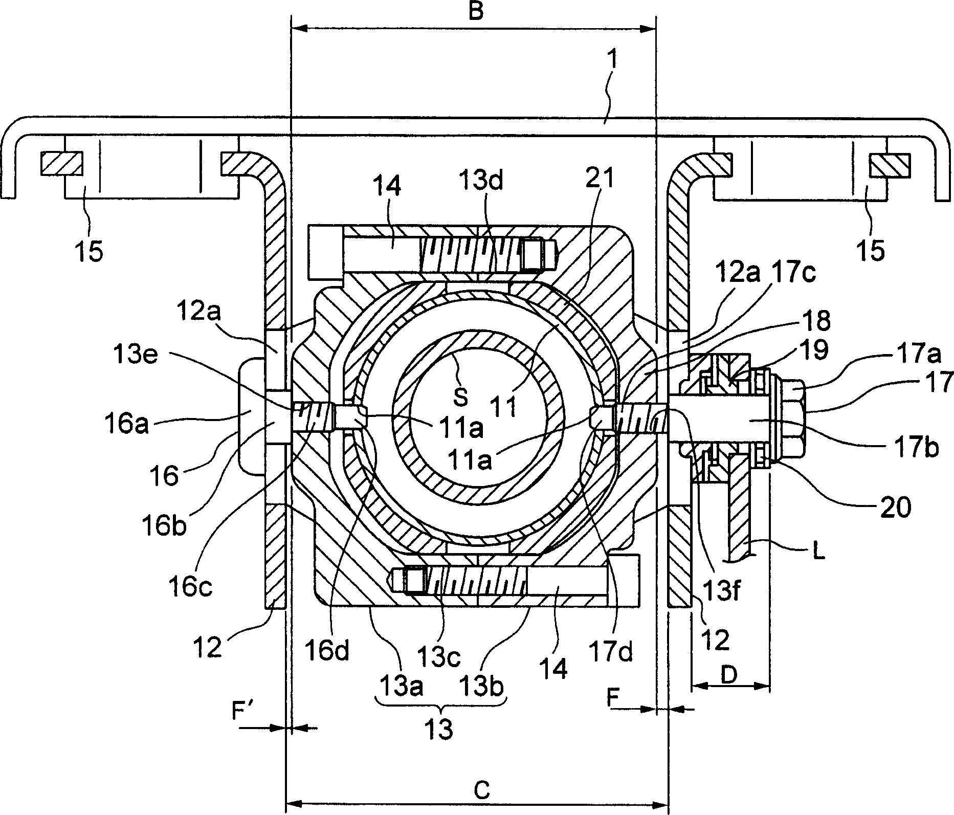
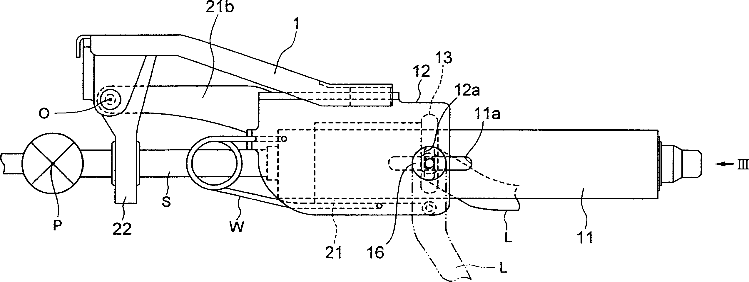
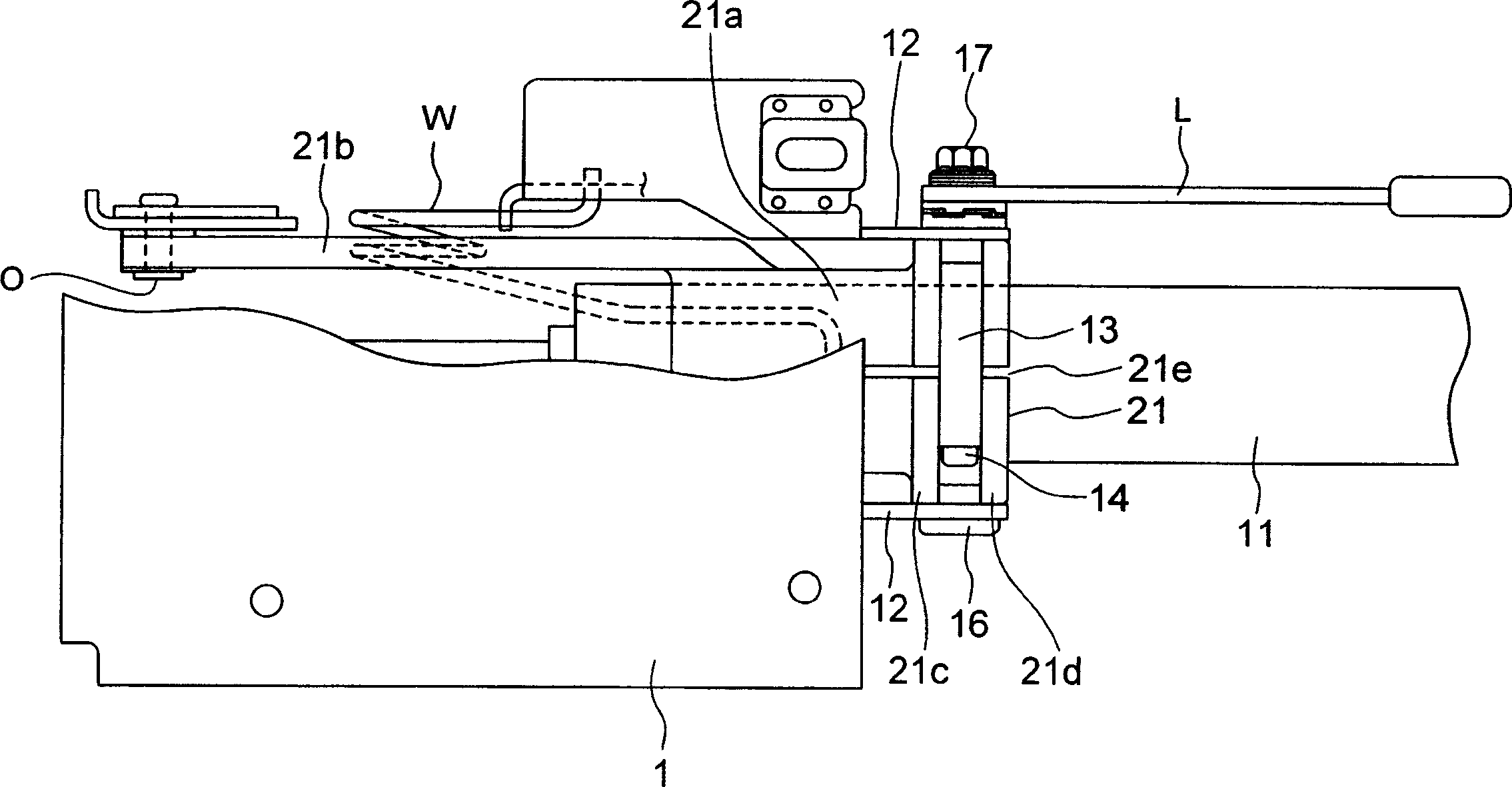
[0030] A tilt / telescopic type steering device according to an embodiment of the present invention will be described below with reference to the accompanying drawings. figure 1 is a sectional view of the tilt / telescopic type steering apparatus according to the first embodiment of the present invention. figure 2 yes figure 1 Side view of the steering gear shown in . image 3 yes figure 1 A top view of the steering gear shown in . Figure 4 is observed along the direction indicated by arrow III figure 2 A view of the steering gear shown in .

[0031] refer to figure 1 , two brackets 12 each formed of a plate-like material are bent into an L-shape, and the two brackets are mounted via a pair of release capsules 15 to a roof panel 1 fixed to the vehicle body, not shown. The plate thickness of each bracket 12 is the same, and the brackets 12 take such a structure that they are line-symmetrical with respect to the vertical line. The release enclosure 15 acts under a secondar...


PUM


Abstract

The invention discloses a steering device comprising an outer column held between a tensioning element (13) and a bracket (12) by an operating rod (L) to prevent movement of the fixed elements (16, 17) along the inclined groove (12a) (21), and the inner column (11) that is held relative to the bracket (12) by the outer column (21) to prevent the fixed elements (16, 17) from moving along the telescopic slot (11a), so in the direction of inclination and telescopic direction Secure the steering shaft (S). When the lever (L) is operated, since the bracket (12) applies pressure to the inner column (11) through the flange portion (21c, 21d) of the outer column (21), the inner column (11) is The approaching direction is subjected to pressure in the opposite direction, and since the rigidity of the pair of brackets (12) is substantially equal, the center of the inner column (11) can be substantially held at a constant position, and thus the steering shaft (S) Axis misalignment can be suppressed.

Description

technical field [0001] The present invention relates to a tilt / telescopic type steering device capable of adjusting the tilt angle of a steering wheel and its axial position relative to a driver's driving posture (position). Background technique [0002] A steering device known for automobiles is a tilt / telescopic type steering device, which makes it possible to adjust the inclination angle of the steering wheel and its axial position in relation to the driver's build and driving posture. [0003] In this respect, in order to guarantee a certain amount of space in the vicinity of the driver's knees, it is desirable to place the elements of the tilt / telescopic type of steering as close as possible to the steering axis. Based on this idea, Japanese Patent Application Laid-Open No. 2001-191927 discloses a steering device configured such that a support member provided in a steering column is placed between a pair of brackets and formed along an inclined groove or edge formed in ...

Claims


Application Information

Patent Timeline
Patent Type & Authority Applications(China)
IPC IPC(8): B62D1/18B62D1/184B62D1/187
CPCB62D1/184B62D1/187
Inventor 池田周平佐藤健司
Owner NSK LTD
Learn More