Working truck

A hydraulic shifting technology for working vehicles, which is applied to construction vehicles, gear transmissions, fluid transmissions, etc., can solve the problems of increased shifting operating force and poor output efficiency, so as to improve operating capabilities, improve low-speed driving performance, High effect of stepless speed change

Inactive Publication Date: 2005-05-11
YANMAR AGRICULT EQUIP CO LTD
View PDF0 Cites 14 Cited by
  • Summary
  • Abstract
  • Description
  • Claims
  • Application Information

AI Technical Summary

Problems solved by technology

[0002] For example, there is a technology of synthesizing and outputting the output of the hydraulic transmission mechanism and the output of the gear transmission through the differential action of the planetary gear mechanism, so that the output of the engine is transmitted at a variable speed, and the speed is set, so that the synthesized output from the planetary gear mechanism The output rotates forward and reverse with stop positions (zero positions) in order to obtain high power transmission efficiency and continuously variable speeds that can advance to zero positions. However, when the combined output from the planetary gear mechanism is on the reverse side, the output from the planetary gears The hydraulic transmission power returns to the pump shaft, and the hydraulic pump rotates, which reduces the shifting operation force of the hydraulic shifting mechanism, but the output efficiency is poor
In addition, when the hydraulic transmission power from the planetary gear is 0 at the medium speed, and at the high speed when the power is transmitted from the hydraulic transmission mechanism to the planetary gear, although the output efficiency is good, the shift operation force increases.

Method used


Image

  • Working truck
  • Working truck
  • Working truck

Examples


Embodiment Construction

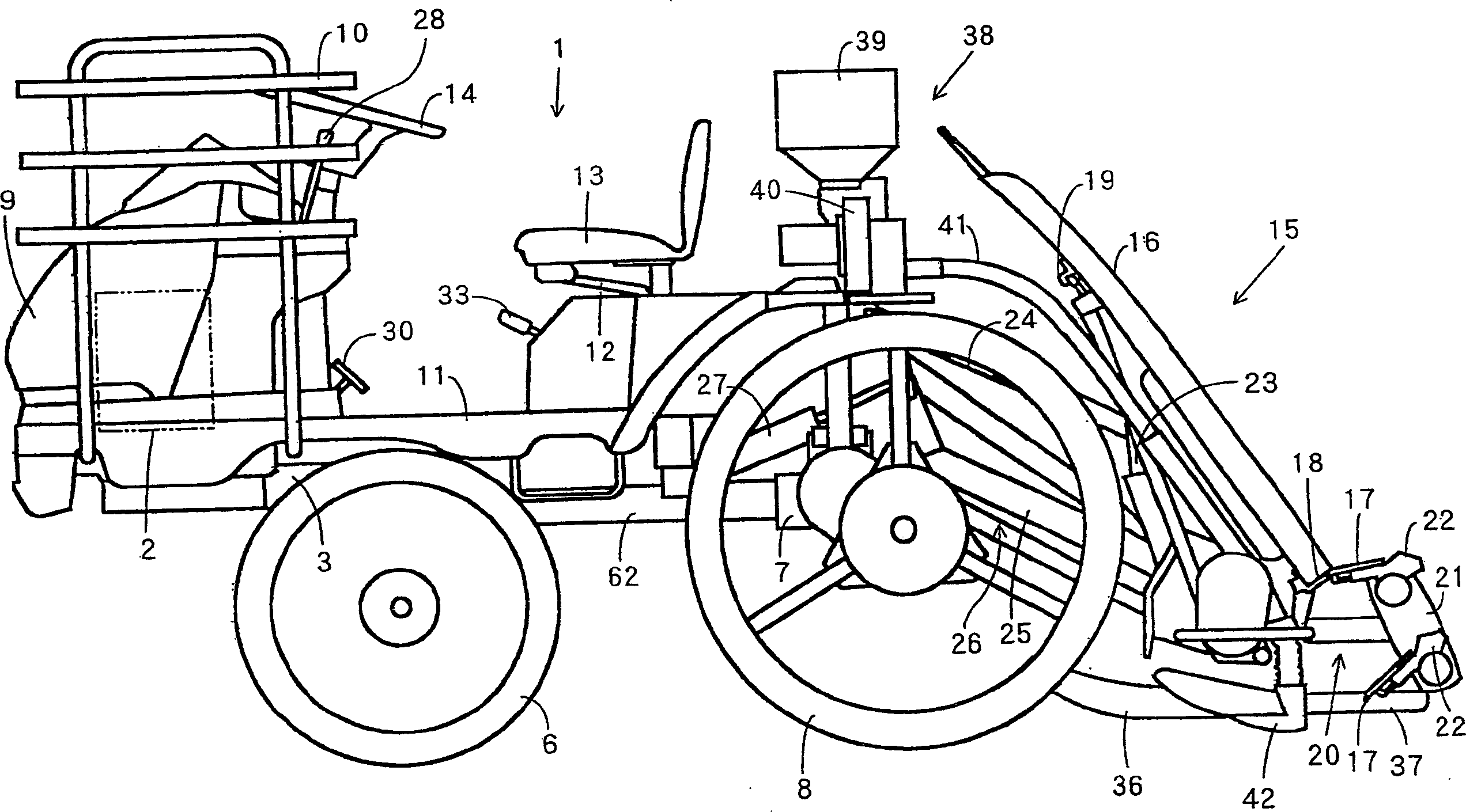
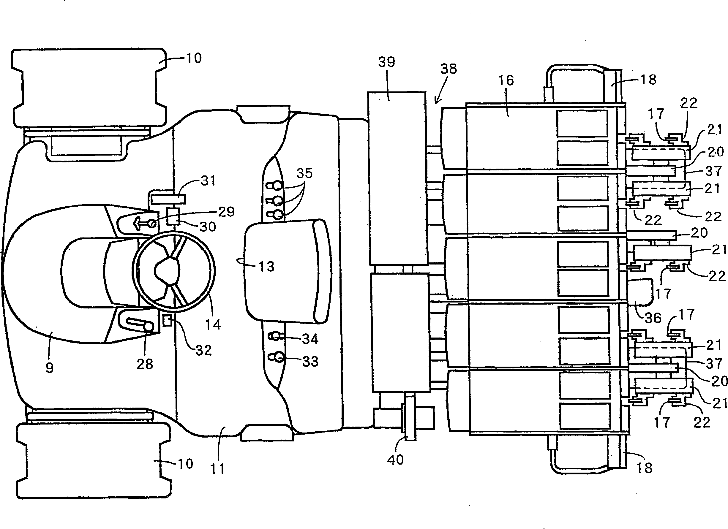
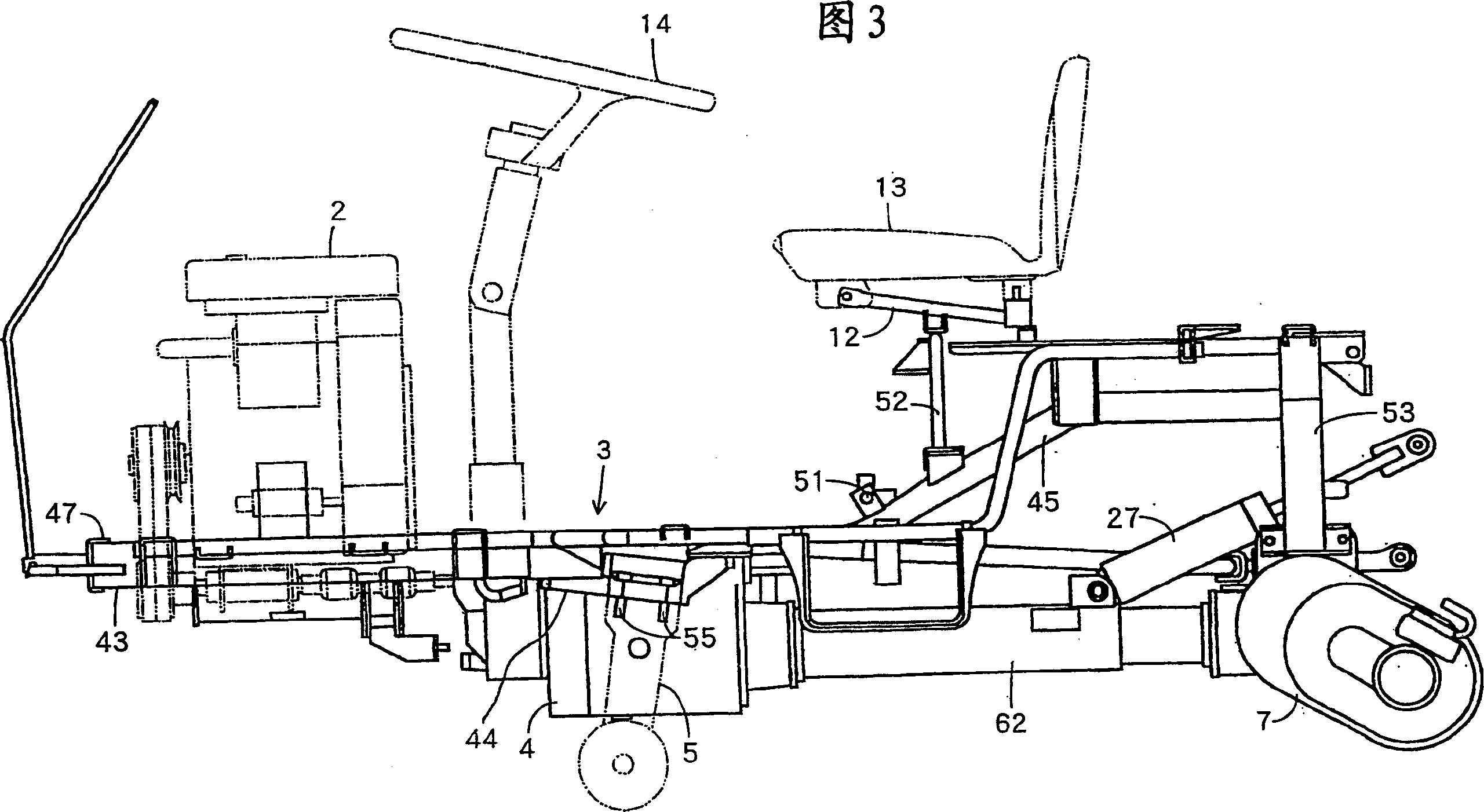
[0036] Embodiments of the present invention will be described in detail below with reference to the accompanying drawings. figure 1 is the overall side view, figure 2 It is the same top view, and Fig. 3 is a side view of the vehicle body frame, and Fig. 4 shows the same top view, among which 1 is a traveling vehicle on which the operator takes, the engine 2 is mounted on the vehicle body frame 3, and the paddy fields travel with the front wheels 6 The front axle case 5 is supported on the side of the transmission case 4, and at the same time, the rear wheel 8 for paddy field driving is supported on the rear axle case 7 behind the above-mentioned transmission case 4. Like this, at the both sides of the hood 9 that covers above-mentioned engine 2 etc., install preparatory seedling-carrying platform 10, simultaneously, cover above-mentioned transmission box 4 etc. by the vehicle body cover 11 that operator rides on, driver's seat 13 is passed through seat frame. 12, installed a...


PUM


Abstract

A hydraulic transmission mechanism (57) and a transmission gear (74) for transmitting the driving force of the engine (2) are provided, and the respective outputs of the hydraulic transmission mechanism (57) and the transmission gear (74) are synthesized to form a transmission output. (74), to obtain the output of high power transmission efficiency, use the above-mentioned hydraulic transmission mechanism (57), obtain the output of the stepless speed change that can advance zero position, with simple speed change operation, carry out speed adjustment according to the situation, seek the speed change function To improve and improve operability, etc., at the same time, through each output of forward rotation or reverse rotation of the hydraulic transmission mechanism (57), the composite output shaft (84) is rotated in one direction, and the composite output shaft (84) composite hydraulic transmission mechanism (57) and transmission gear (74) each output, carry out variable speed output, ensure the output torque when zero position advances easily, improve microspeed driving performance easily, and effectively utilize the high power of transmission gear (74) at working speed The output of transmission efficiency seeks to improve the working ability on dirt roads, etc.

Description

technical field [0001] The present invention relates to a working vehicle including a rice planting platform, a rice transplanting claw, a rice transplanter, a tractor, a combine harvester, or a civil engineering machine for performing continuous rice transplanting, for example. Background technique [0002] For example, there is a technology of synthesizing and outputting the output of the hydraulic transmission mechanism and the output of the gear transmission through the differential action of the planetary gear mechanism, so that the output of the engine is transmitted at a variable speed, and the speed is set, so that the synthesized output from the planetary gear mechanism The output rotates forward and reverse with stop positions (zero positions) in order to obtain high power transmission efficiency and continuously variable speeds that can advance to zero positions. However, when the combined output from the planetary gear mechanism is on the reverse side, the output ...

Claims


Application Information

Patent Timeline
Patent Type & Authority Applications(China)
IPC IPC(8): F16H3/083F16H47/04
CPCB60Y2200/41F16H3/083F16H47/04F16H2037/0886
Inventor 前川智史松冈秀树井上诚山下钢丈
Owner YANMAR AGRICULT EQUIP CO LTD
Why Eureka
Try Eureka