

Swinging or reciprocating type manpower driven device
A human-driven, reciprocating technology, applied in the directions of rider driving, transportation and packaging, vehicle parts, etc., can solve problems such as inability to do work, easy fatigue, and large force loss
- Summary
- Abstract
- Description
- Claims
- Application Information
AI Technical Summary
Problems solved by technology
Method used
Image

Examples
Embodiment 1
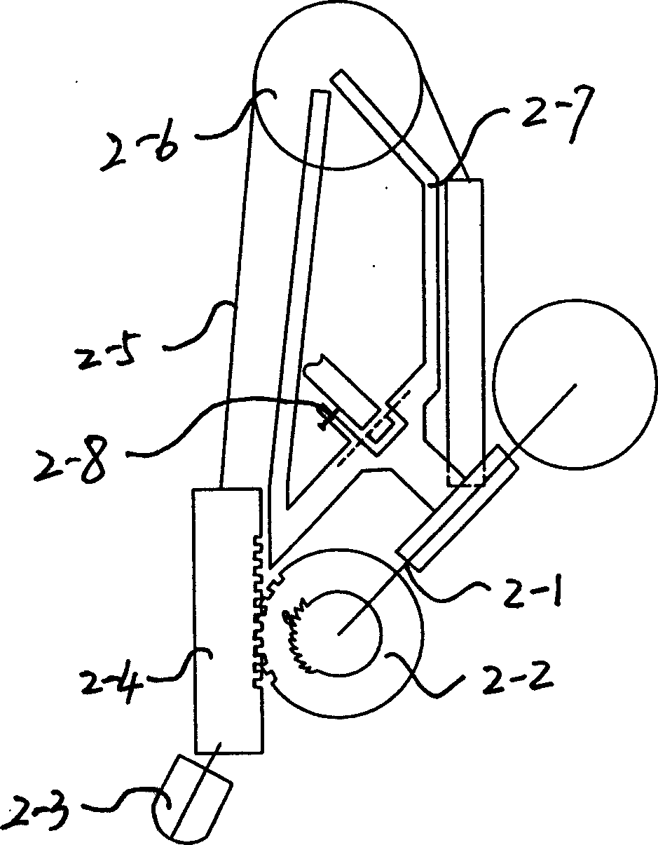
[0029] Embodiment 1, as figure 2 As shown, the original bicycle crutch pedal is discarded, and a flywheel 2-2 is respectively established at the original bicycle axis 2-1 two ends and the crutch connection point; (the effect of the flywheel should ensure that the active force drives the bicycle to move forward), The front of the rack is provided with a rack 2-4 along the vertical direction, the rack is installed on the rack guide rail, the outer end of the rack is equipped with a pedal 2-3, and the upper part is provided with a device connecting the upper and lower safeguard devices; An upper and lower protection mechanism is arranged at an appropriate position above the bar, and the upper and lower protection mechanism is composed of an intermediate transition wheel 2-6 and a stay rope 2-5. , The length of the upright and connected levers of the guarantee device is used to adjust the pedal stroke and stroke center. In order to make the bicycle when going uphill, the tooth b...
Embodiment 2
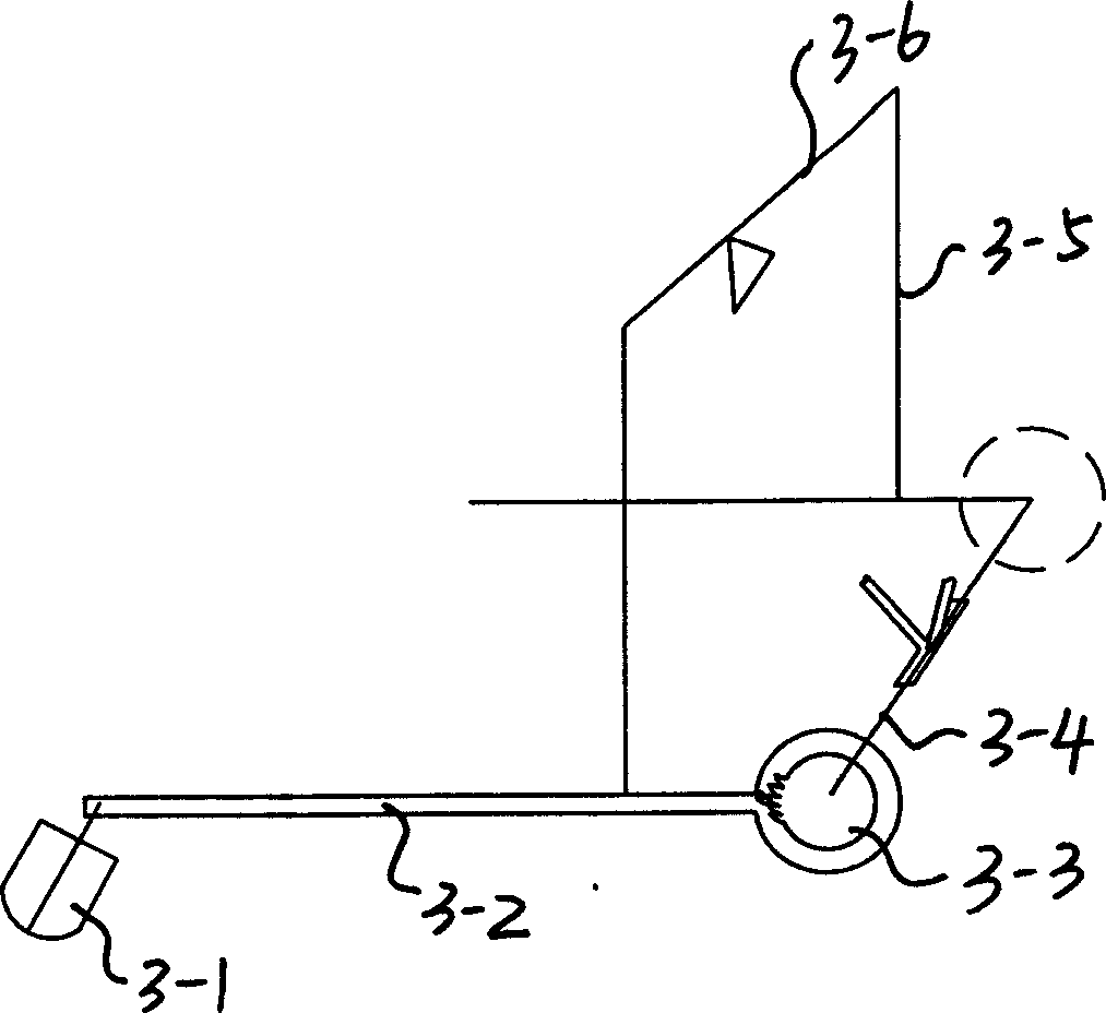
[0030] Embodiment 2, as image 3 As shown in the original bicycle left and right crutches 3-2 and the central shaft 3-4, respectively install a flywheel composed of a ratchet pawl 3-3 structure, the inner side of the flywheel is connected with the central shaft 3-4, and the outer side is connected with the crutches. 3-2 connected, when one side of the crutch travels down, the flywheel drives the central axis to rotate, and at the same time, the crutches up and down protection mechanism is composed of lever 3-6 and connecting rod 3-5, driving the other crutch to go back up, When the crutches go up, the flywheel is in the clutch state, and the crutches up and down protection mechanism is set between the two crutches. Like the up and down protection mechanism of the rack, the crutches guarantee mechanism also ensures that the strokes of the left and right pedals are in a straight line, and the left and right crutches One down and one up, the central axis is driven to rotate throu...
Embodiment 3
[0032] Embodiment 3, as Figure 6Shown, discard the central axis, large chain disc, chain and flywheel of the original bicycle, and a flywheel 6-3 is respectively adorned outside the vehicle frame at the two ends of the bicycle rear axle 6-4, between the rear axle 6-4 and the vehicle frame The bearing is connected, and a set of deceleration and transmission device is arranged between the rear wheel hub to be connected with the rear wheel hub. The inner side of the flywheel 6-3 is fixedly connected with the rear wheel shaft 6-4, and the outer side is connected with the foot turn 6-2, and the foot turn 6-2 is provided with a foot Step 6-1, establish a set of left and right crutches up and down guarantee device between two crutches, be made up of lever 6-6 and connecting rod 6-5. The rear wheels are driven to rotate by the up and down swing of the left and right crutches.
[0033] Foot crutches can also be fixed with a minor axis 7-3 along the front of the rear axle level, and a...
PUM
 Abstract
Description
Claims
Application Information