
Page rotating method of printing operation

A technology for printing jobs and jobs, applied in the direction of digital output to printing units, instruments, optics, etc., can solve the problems of inconvenient use, unacceptable speed, unacceptable special chip methods, etc., to avoid time-consuming operations.

Inactive Publication Date: 2005-06-08
BEIJING FOUNDER ELECTRONICS CO LTD +1
View PDF0 Cites 5 Cited by
  • Summary
  • Abstract
  • Description
  • Claims
  • Application Information

AI Technical Summary

Problems solved by technology

In low-end printers, usually only one of LEF or SEF is supported, which brings inconvenience to use; there are also some low-end printers that use a method similar to high-end systems, that is, use a dedicated chip to rotate the dot matrix, otherwise The speed is unacceptable, because a monochrome dot matrix of A4 600DPI format needs 16M memory, and high-end movement generally uses multi-bit interface, and 128M memory is required to print a page with 8-bit interface
Using a dedicated chip will not only increase the cost of the printing system, but also cannot be adopted in an environment that uses a rasterization module (RIP)

Method used


Image

  • Page rotating method of printing operation
  • Page rotating method of printing operation
  • Page rotating method of printing operation

Examples


Embodiment Construction

[0021] The present invention will be further described below in conjunction with accompanying drawing and embodiment, but present embodiment is not in order to limit the present invention:

[0022] Such as Figure 5 The illustrated embodiment introduces the following components to realize the method of the present invention:

[0023] The front-end software 50 refers to an application program that supports printing on operating systems such as Windows or Macintosh, such as Word or PageMaker, etc.;

[0024] 51 refers to the rasterization module RIP;

[0025] The print manager 52 refers to a module that realizes the page rotation processing function of the present invention;

[0026] PPD53 refers to the Postscript printer description file, which describes the characteristics of the printer, such as the type of paper supported by the printer, whether the printer supports binding, etc.;

[0027] The core 54 refers to the device that transfers the dot matrix after RIP to the pape...


PUM


Abstract

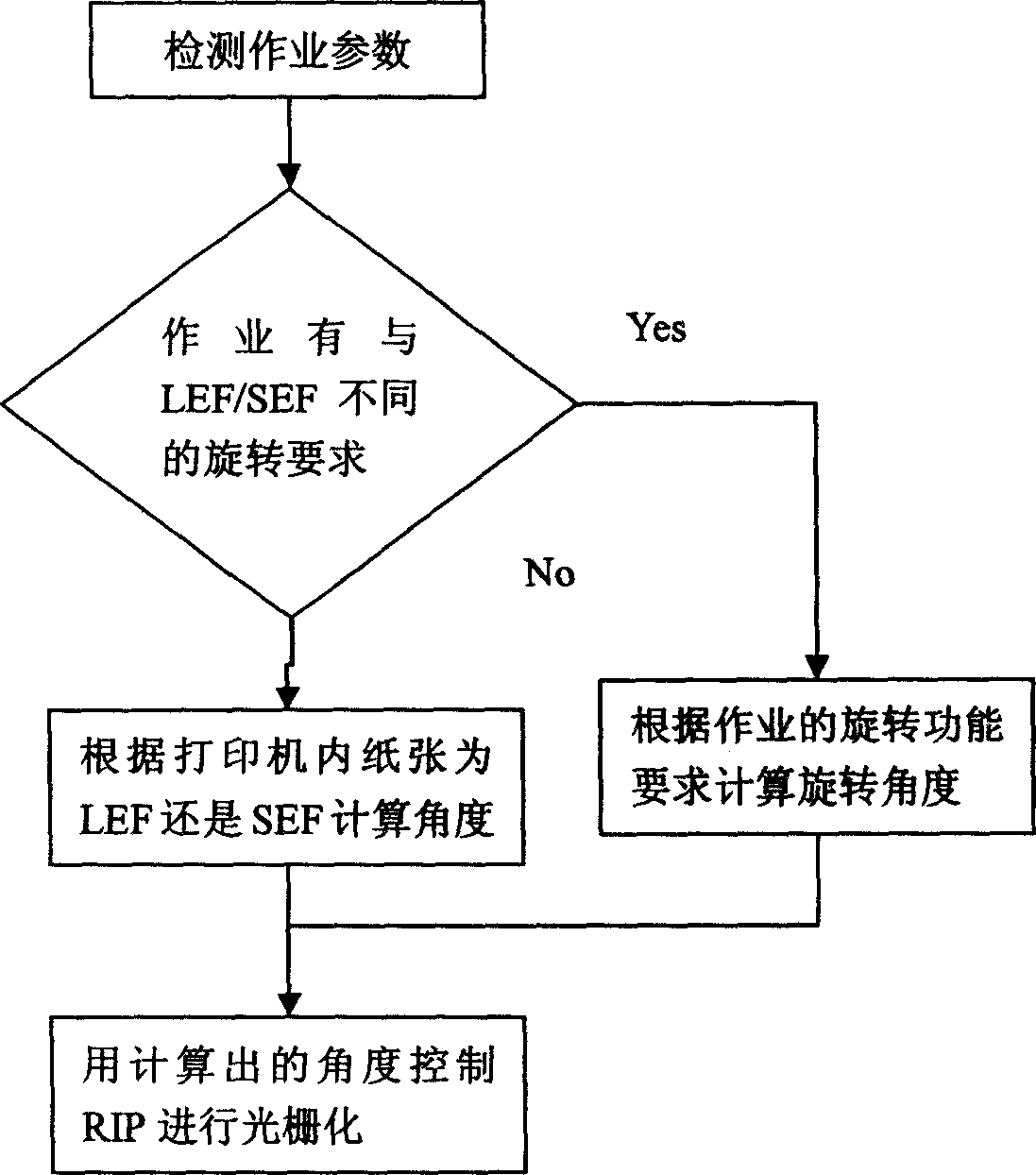
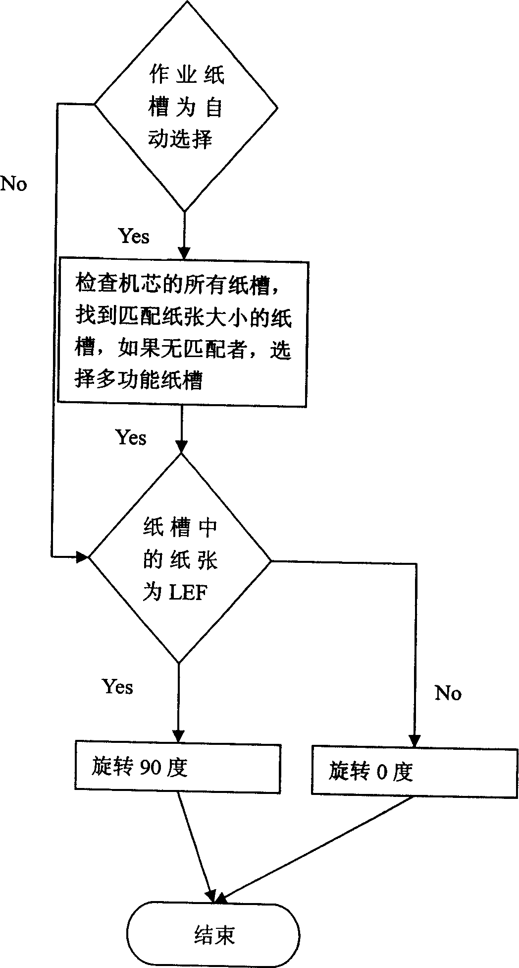
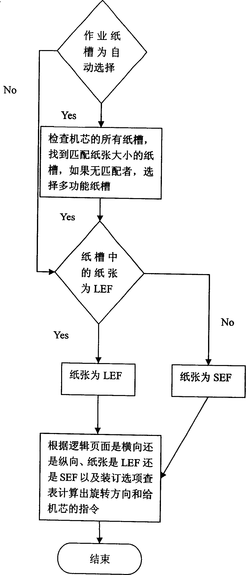
The invention relates to a page rotation method of printing. The method applied in the invention can satisfy the requirements of different rotating functions, avoid the front terminal software meeting the paper type which can not be understood when process with long-edge or short-edge of paper entering work or that needs special rotating function. Besides, the use of profession chip or rotating point array which is wasting time can be avoided which results from calculating the rotating angle before RIP.

Description

technical field [0001] The invention belongs to the field of graphics and image printing, and in particular relates to a page rotation method for printing jobs. Background technique [0002] In the prior art, print output devices usually provide two paper feed modes, which are called LEF (LongEdge Feed, long edge feed) and SEF (Short Edge Feed, short edge feed), respectively. In the paper slot, it is displayed as horizontal placement and vertical placement respectively. Because the paper in the printing process has to go through the transfer drum for latent image transfer and subsequent fixing steps, one way to increase the printing speed is to reduce the path of the printing paper in the core, so the high-speed core usually provides LEF And SEF two ways, in which the path of paper in the machine core is shorter in LEF mode, and the printing speed is faster. Just like the paper placement of LEF and SEF, the scanning data required by the two methods also differ by 90 degree...

Claims


Application Information

Patent Timeline
Patent Type & Authority Applications(China)
IPC IPC(8): G03G21/14G06F3/12
Inventor 李洪伟王立东赵晖陈峰
Owner BEIJING FOUNDER ELECTRONICS CO LTD
Learn More