Composite pressure pipe

A composite pipe, pressure-resistant technology, applied in the direction of hoses, pipes, rigid pipes, etc., can solve the problems of complicated manufacturing process, and achieve the effect of improving pressure resistance performance, realizing manufacturing process, and high pressure resistance performance.

Inactive Publication Date: 2005-06-22
TOTAKU IND INC
View PDF1 Cites 10 Cited by
  • Summary
  • Abstract
  • Description
  • Claims
  • Application Information

AI Technical Summary

Problems solved by technology

Therefore, there is a disadvantage that the manufacturing process of the tube is complicated

Method used


Image

  • Composite pressure pipe
  • Composite pressure pipe
  • Composite pressure pipe

Examples


Embodiment Construction

[0028] Embodiments of the present invention will be described in detail below based on the drawings. The pressure-resistant composite pipe according to Embodiment 1 of the present invention is used, for example, as a drainage pipe buried underground.

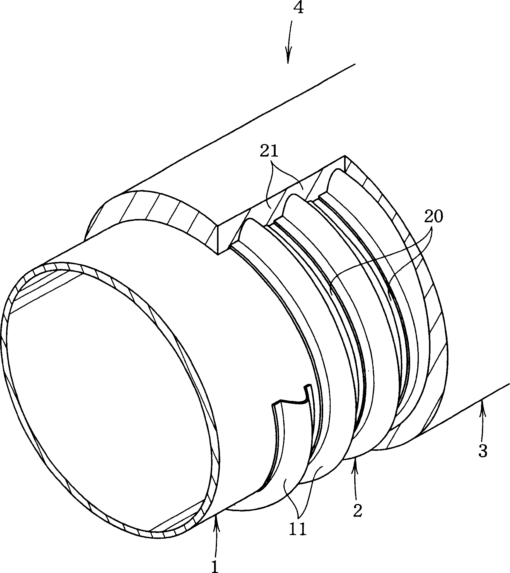
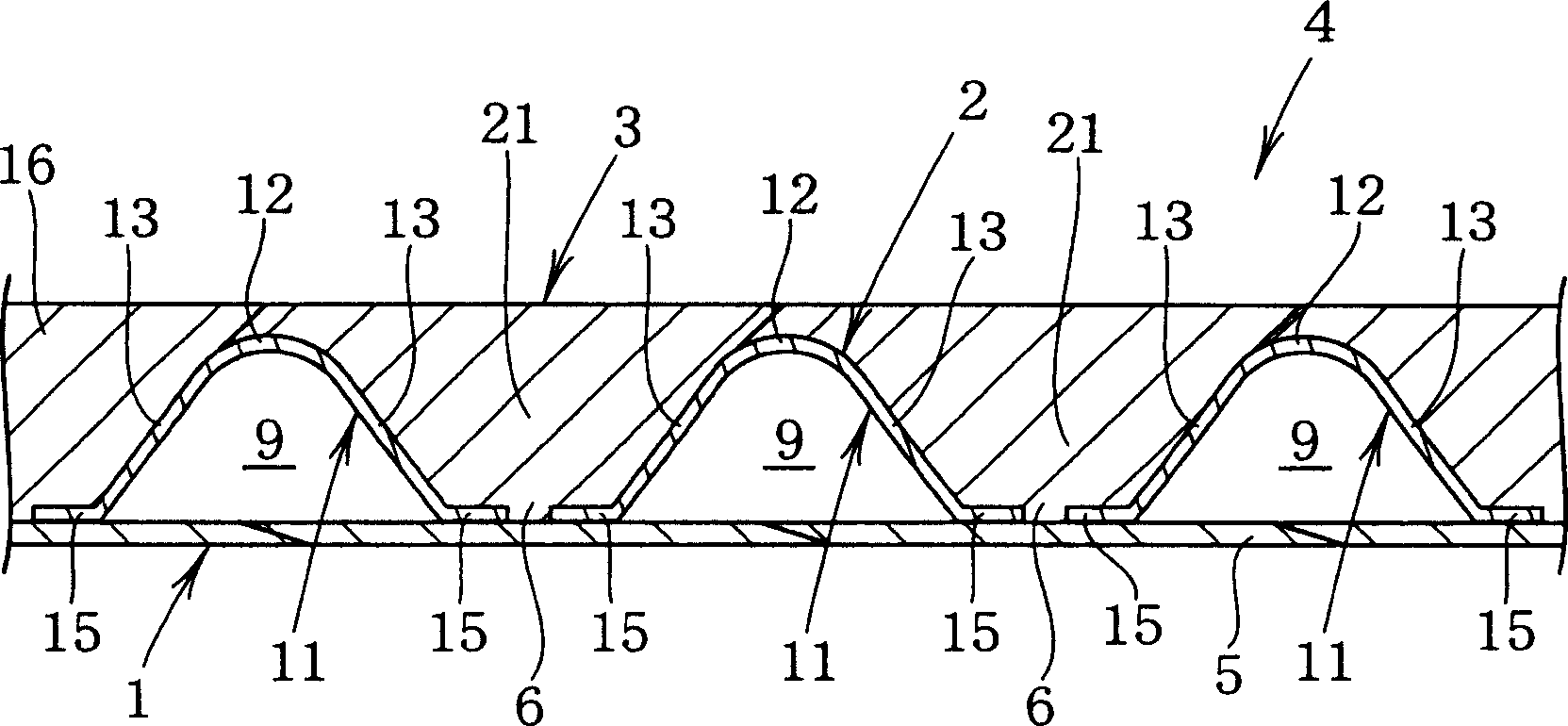
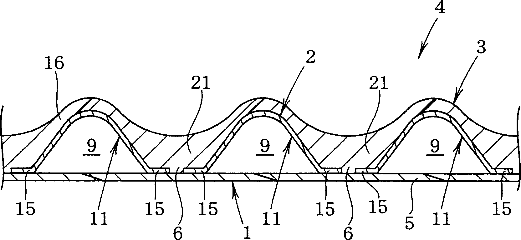
[0029] like figure 1 and 2 As shown, this pressure-resistant composite pipe includes an inner layer 1 made of synthetic resin, a metal belt-shaped reinforcement plate 2 provided along the outer peripheral surface of the inner layer 1, and a belt-shaped reinforcement plate 2 that covers the belt-shaped reinforcement plate 2. The pipe wall 4 is formed by the outer layer 3 made of synthetic resin on the outer peripheral surface.

[0030] The inner layer 1 can be constituted by, for example, helically winding a synthetic resin band 5 made of polyethylene resin, and thermally welding adjacent side edges along the tube axis direction. . However, instead of heat welding, the side edge portions may be joined to each other by adhesio...


PUM


Abstract

The present invention provides a pressure-resistant composite pipe comprising an inner layer (1) made of synthetic resin and a metal belt wound annularly or helically along the outer peripheral surface of the inner layer (1). A strip-shaped reinforcing plate (2), and a synthetic resin outer layer (3) covering the outer peripheral surface of the strip-shaped reinforcing plate (2). The strip-shaped reinforcing plate (2) continuously has a convex portion (11) expanding radially outward in the longitudinal direction. The outer layer (3) has a buried portion (21) that fills a concave portion (20) formed between adjacent convex portions (11, 11) in the tube axial direction. Therefore, the pressure-resistant composite pipe not only has a simple structure, but also can effectively suppress the deformation of the belt-shaped reinforcing plate when the external pressure acts, thereby exhibiting high pressure-resistant performance.

Description

technical field [0001] The present invention relates to a pressure-resistant composite pipe mainly suitable for drainage pipes or cable protection pipes buried underground. Background technique [0002] Conventionally, a pressure-resistant composite pipe in which a metal strip-shaped reinforcing plate is embedded in a pipe body of a synthetic resin corrugated pipe to improve pressure resistance is known as a drainage pipe or cable protection pipe buried underground. [0003] As disclosed in Patent Document 1, in this type of composite pipe, a strip-shaped reinforcing plate continuously provided with protrusions expanding in the radially outward direction in the longitudinal direction is formed so that the edge portions facing each other in the pipe axial direction are separated. Separated from each other and wound into a helical shape with a certain gap. Furthermore, in this composite pipe, flexibility is well maintained by providing a portion made of only a synthetic resin...

Claims


Application Information

Patent Timeline
Patent Type & Authority Applications(China)
IPC IPC(8): E03F3/04F16L9/04F16L9/128F16L9/14F16L9/147F16L9/16F16L11/08F16L11/115F16L11/118F16L11/15F16L11/20H02G9/06
CPCF16L9/147F16L11/081F16L11/115F16L11/118F16L11/15F16L11/20F16L9/14F16L9/04F16L9/128
Inventor 桝井宏之町野达也坂根泰平尾升司林义晃
Owner TOTAKU IND INC
Why Eureka
Try Eureka