Laser divergence angle measuring instrument and measuring method

A measurement method and laser technology, applied in the direction of testing optical performance, etc., can solve the problems of narrow measurement range and low accuracy, and achieve the effect of improving test accuracy and small detection range

Inactive Publication Date: 2005-07-06
INST OF SEMICONDUCTORS - CHINESE ACAD OF SCI
View PDF0 Cites 22 Cited by
  • Summary
  • Abstract
  • Description
  • Claims
  • Application Information

AI Technical Summary

Problems solved by technology

[0009] In order to solve the shortcomings of low accuracy and narrow measurement range of existing divergence angle measurement methods, the purpose of the present invention is to provide a divergence angle measur

Method used


Image

  • Laser divergence angle measuring instrument and measuring method
  • Laser divergence angle measuring instrument and measuring method
  • Laser divergence angle measuring instrument and measuring method

Examples


Embodiment Construction

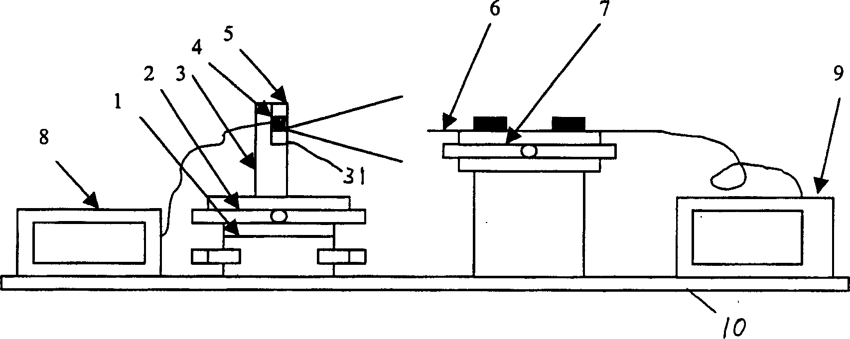
[0038] see figure 1 , figure 2 , image 3 , Figure 4 and Figure 5 Shown, a kind of laser divergence angle measuring instrument of the present invention comprises:

[0039] A rotary fine-tuning frame 1, the rotary fine-tuning frame 1 can be rotated and fine-tuned, and the rotary fine-tuning frame 1 is installed on the base 10 ( figure 1 middle);

[0040] A two-dimensional fine-tuning frame 2 is fixed on the rotating fine-tuning frame 1, and the two-dimensional fine-tuning frame 2 can be fine-tuned in the X and Y axis directions;

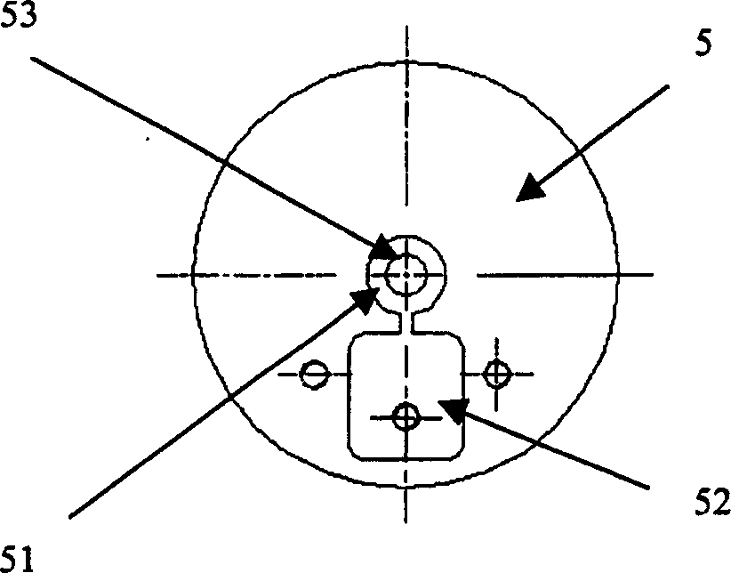
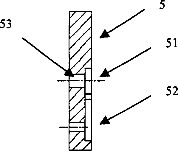
[0041] A cylindrical fitting 3, which is fixed on the two-dimensional fine-tuning frame 2, and has a circular groove 31 ( Figure 4 , Figure 5 middle); wherein in the circular groove 31 of the cylindrical fitting 3, a circular clamp 5 is inserted and fitted, and a circular groove 51 is arranged in the middle of the circular clamp 5 ( figure 2 , image 3 Middle), there is a square groove 52 below the circular groove 51, the square groove ...


PUM


Abstract

This invention relates to laser divergence angle measurement device, which comprises the following: one rotation micro-adjusting frame fixed on the socket; one two-dimensional adjusting frame on the rotation frame; one column counterpart fixed on the two-dimensional frame with a round groove on it; one three-dimensional adjusting frame fixed on the socket; one conical fiber on the three-dimensional frame; one constant power fixed on the socket; one power meter connected to the optical fiber and fixed on the socket.

Description

Technical field [0001] The invention belongs to the technical field of optoelectronic device manufacturing technology, and more specifically relates to a laser divergence angle measuring instrument and a measuring method thereof. Background technique [0002] In the preparation process of semiconductor lasers for optical fiber communication, the performance parameters of the core component laser chip directly determine the performance of the entire device and module. [0003] The outgoing beam of the laser chip has a certain divergence angle, and has different angles in the X and Y directions. In order to improve the coupling efficiency of the laser beam and the optical fiber, a lens is usually placed on the optical axis of the outgoing beam, and a spherical or aspheric lens is used according to the laser beam and process requirements. For different batches of laser chips, the divergence angles are not consistent, and the size and parameters of the lens are fixed. In order...

Claims


Application Information

Patent Timeline
IPC IPC(8): G01M11/02
Inventor 祝宁华宋海鹏刘戬袁海庆
Owner INST OF SEMICONDUCTORS - CHINESE ACAD OF SCI
Why Eureka
Try Eureka