A liquid crystal dish structure

A liquid crystal and liquid crystal material technology, applied in nonlinear optics, instruments, optics, etc., can solve the problems of too many liquid crystal materials and waste of liquid crystal material production costs, and achieve the effect of reducing usage, improving injection efficiency, and reducing production costs

Inactive Publication Date: 2005-07-06
CHUNGHWA PICTURE TUBES LTD
View PDF2 Cites 1 Cited by
  • Summary
  • Abstract
  • Description
  • Claims
  • Application Information

AI Technical Summary

Problems solved by technology

[0005] The technical problem to be solved by the present invention is to provide a liquid crystal cell structure to solve the problem of incre

Method used


Image

  • A liquid crystal dish structure
  • A liquid crystal dish structure
  • A liquid crystal dish structure

Examples


Embodiment Construction

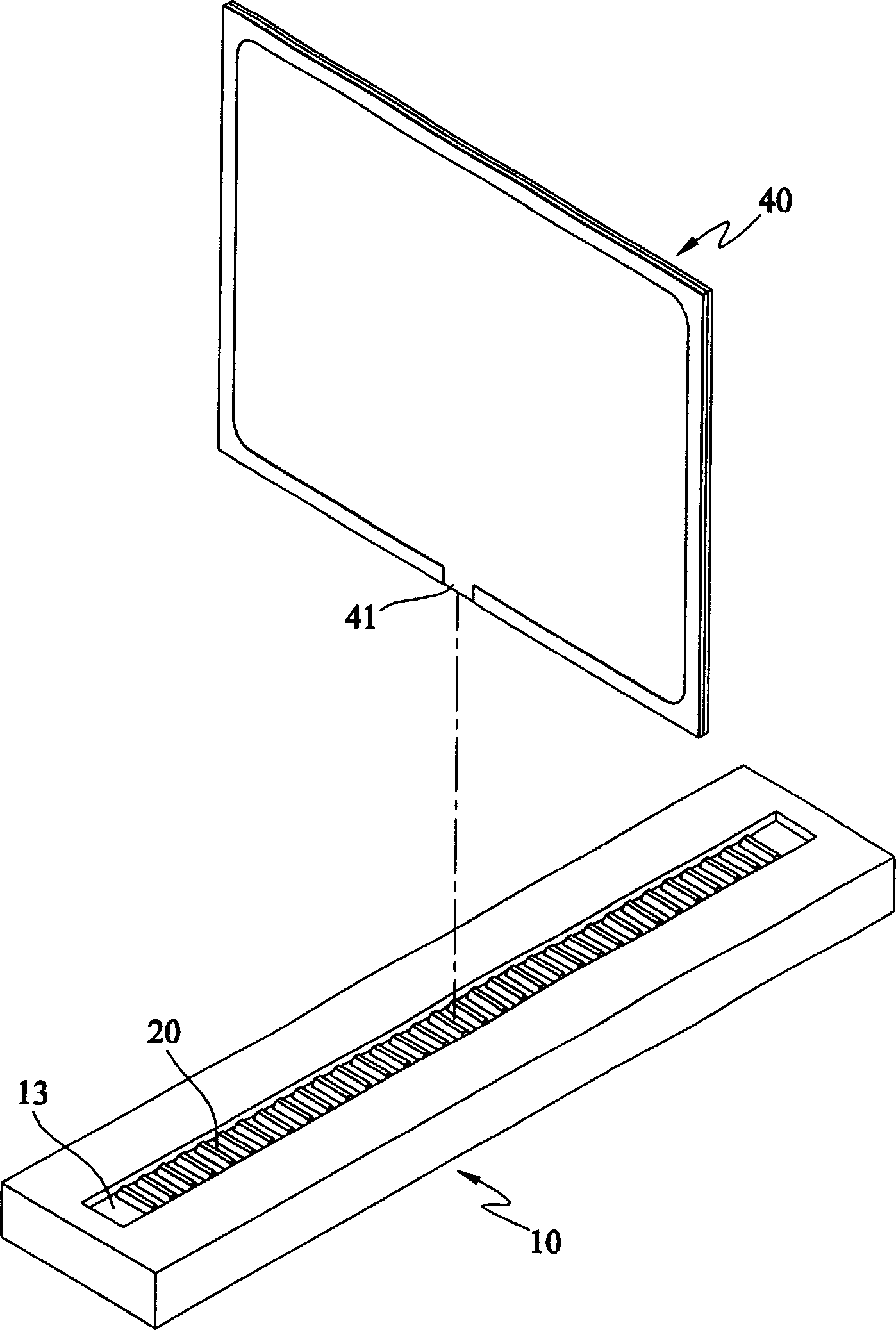
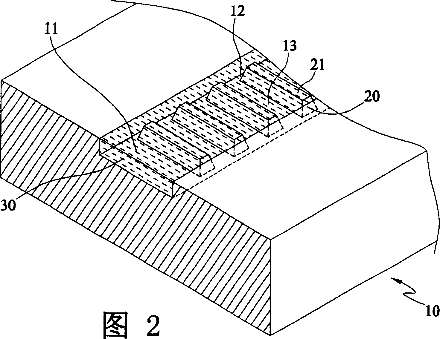
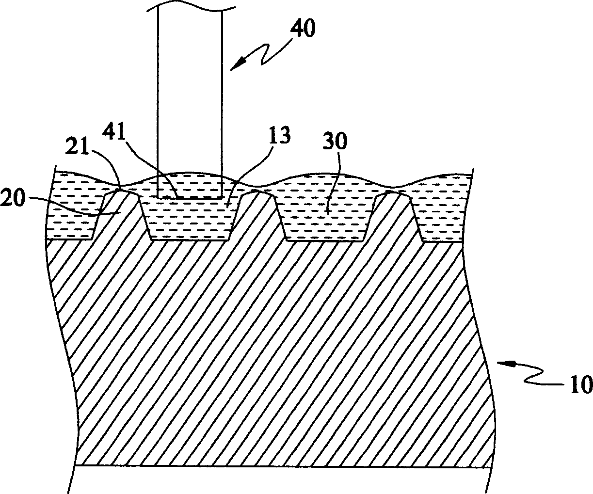
[0024] According to a kind of liquid crystal cell structure disclosed by the present invention, please refer to figure 1 2 to illustrate the first preferred embodiment, wherein the liquid crystal cell 10 has an injection tank 11 for containing liquid liquid crystal material (Liquidcrystal material), the bottom side of the injection tank 11 has several intervals, solid trapezoidal three-dimensional The block-shaped protrusion 20 separates the liquid injection groove 11 into several liquid injection chambers 13 . The top side 21 of the bump 20 has a curved surface. A flow channel 12 with an appropriate width is formed between the liquid injection groove 11 and the protrusion 20 , so that the liquid crystal material 30 stored in the liquid injection groove 11 can freely flow between the liquid injection chambers 13 .

[0025] It should be noted that since the bottom side of the liquid injection tank 11 has several protrusions 20, which occupy the volume space of the liquid injec...


PUM


Abstract

This invention discloses a LCD container with injection groove to contain the LCD materials. When the LCD panel is over set above the injection groove, the LCD materials are drawn by siphon phenomenon and vacuum pressure difference. What is more special is that the liquid groove bottom side is located with several interval distributed extrusion blocks to separate the groove into several injection chambers.

Description

technical field [0001] The invention relates to a liquid crystal container, in particular to a liquid crystal cell structure which greatly reduces the amount of liquid crystal material used. Background technique [0002] In recent years, with the prosperity of the electronic industry, the application of computer equipment is no longer a commodity that only a few people can have, but has penetrated into people's lives. Generally speaking, a computer device is composed of a computer mainframe, an input device and a display device. The traditional image display device is based on the cathode ray tube display (Cathode Ray Tube, CRT) as its market mainstream. However, such products have the disadvantages of large size, considerable thickness, flickering of the screen, and the curvature of the screen plane, which makes it difficult to achieve complete equality. Thanks to the advances in semiconductor technology, liquid crystal displays (LCDs) have the advantages of being light, ...

Claims


Application Information

Patent Timeline
IPC IPC(8): G02F1/1333G02F1/1341
Inventor 许时毓张东桂简庆智游英旗
Owner CHUNGHWA PICTURE TUBES LTD
Why Eureka
Try Eureka