Gas generator

A gas generator, gas technology, applied in the direction of vehicle safety arrangement, pedestrian/occupant safety arrangement, transportation and packaging, etc., can solve the problem of high cost

Inactive Publication Date: 2005-07-06
NIPPON KAYAKU CO LTD
View PDF2 Cites 5 Cited by
  • Summary
  • Abstract
  • Description
  • Claims
  • Application Information

AI Technical Summary

Problems solved by technology

The gas generator is equipped with an annular filter device in each combustion chamber, so the cost is high

Method used


Image

  • Gas generator
  • Gas generator
  • Gas generator

Examples


Embodiment Construction

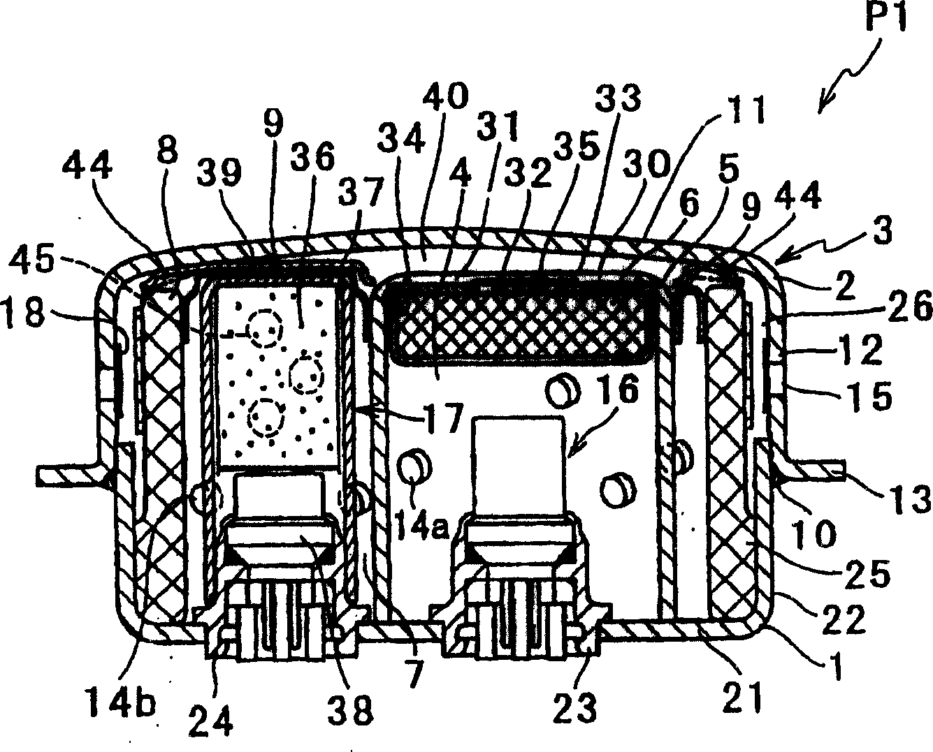
[0022] Hereinafter, embodiments of the gas generator of the present invention will be described with reference to the accompanying drawings.

[0023] figure 1 Shown is a cross-sectional view of the gas generator P1 of Embodiment 1 of the present invention. figure 1 Among them, the gas generator P1 is a generator that inflates and expands the airbag for the driver's seat, and it is composed of the following parts: a cylindrical cover 3 composed of an initiating shell 1 and a closing shell 2; A cylindrical member 5 of the chamber 4; a disc-shaped second filtering device 6 arranged in the cylindrical member 5; a ring-shaped first filter device 6 arranged along the inner periphery of the cover 3 and forming a first combustion chamber 7 inside; A filtering device 8; a spacer member 39 restricting the axial direction of the gas generator in the cover 3; a gas generating agent 14a, 14b filled in each combustion chamber 4, 7; respectively arranged in each combustion chamber 4, 7 The...


PUM


Abstract

A gas generator comprising the following parts: a cylindrical cover (3) composed of an initiation shell (1) and a closing shell (2) with a plurality of ignition devices (16, 17); formed on the cover ( 3) and a combustion chamber filled with gas generating agents (14a, 14b); a cylindrical member that divides the above combustion chamber into two or more combustion chambers (4, 7); The filter device (6, 8) in each combustion chamber (4, 7) above the chamber is characterized in that at least one of the above-mentioned filter devices (6, 8) is disc-shaped, and each of the above-mentioned combustion chambers (4, 7 ) are independent of each other.

Description

technical field [0001] The present invention relates to a gas generator for a condition-adaptive airbag which uses a plurality of igniters to burn a gas generating agent in a cover and to control the inflation and deployment of the airbag. Background technique [0002] In order to protect occupants from the impact of a car collision, the gas generator that rapidly inflates and deploys the airbag is assembled in the airbag module, which is installed in the steering wheel or the instrument panel. The gas generator operates the igniter (detonator) according to the electric signal from the control device (actuator), and uses the flame of the igniter to burn the gas generating agent to generate a large amount of gas rapidly. [0003] The gas generator of the prior art often inflates and deploys the airbag rapidly regardless of the occupant's seating posture (regular seating, irregular seating such as forward bending) and vehicle speed (acceleration) at the time of collision. The...

Claims


Application Information

Patent Timeline
Patent Type & Authority Applications(China)
IPC IPC(8): B60R21/26B60R21/263B60R21/264
CPCB60R21/261B60R21/2644B60R2021/2633B60R2021/2648
Inventor 西村刚一田中耕治
Owner NIPPON KAYAKU CO LTD
Why Eureka
Try Eureka