
Continuously variable transmission

A transmission device, continuously variable speed technology, applied in the transmission device, friction transmission device, transmission device control and other directions, can solve the problem of complex structure of the transmission device, and achieve the effect of ensuring work safety, reliable position measurement, and compact structure

Inactive Publication Date: 2005-07-13
乌尔里克·罗斯
View PDF0 Cites 0 Cited by
  • Summary
  • Abstract
  • Description
  • Claims
  • Application Information

AI Technical Summary

Problems solved by technology

However, in order to adjust the friction ring, a special transmission mechanism is required that makes the structure of the transmission very complicated.

Method used


Image

  • Continuously variable transmission
  • Continuously variable transmission
  • Continuously variable transmission

Examples


Embodiment Construction

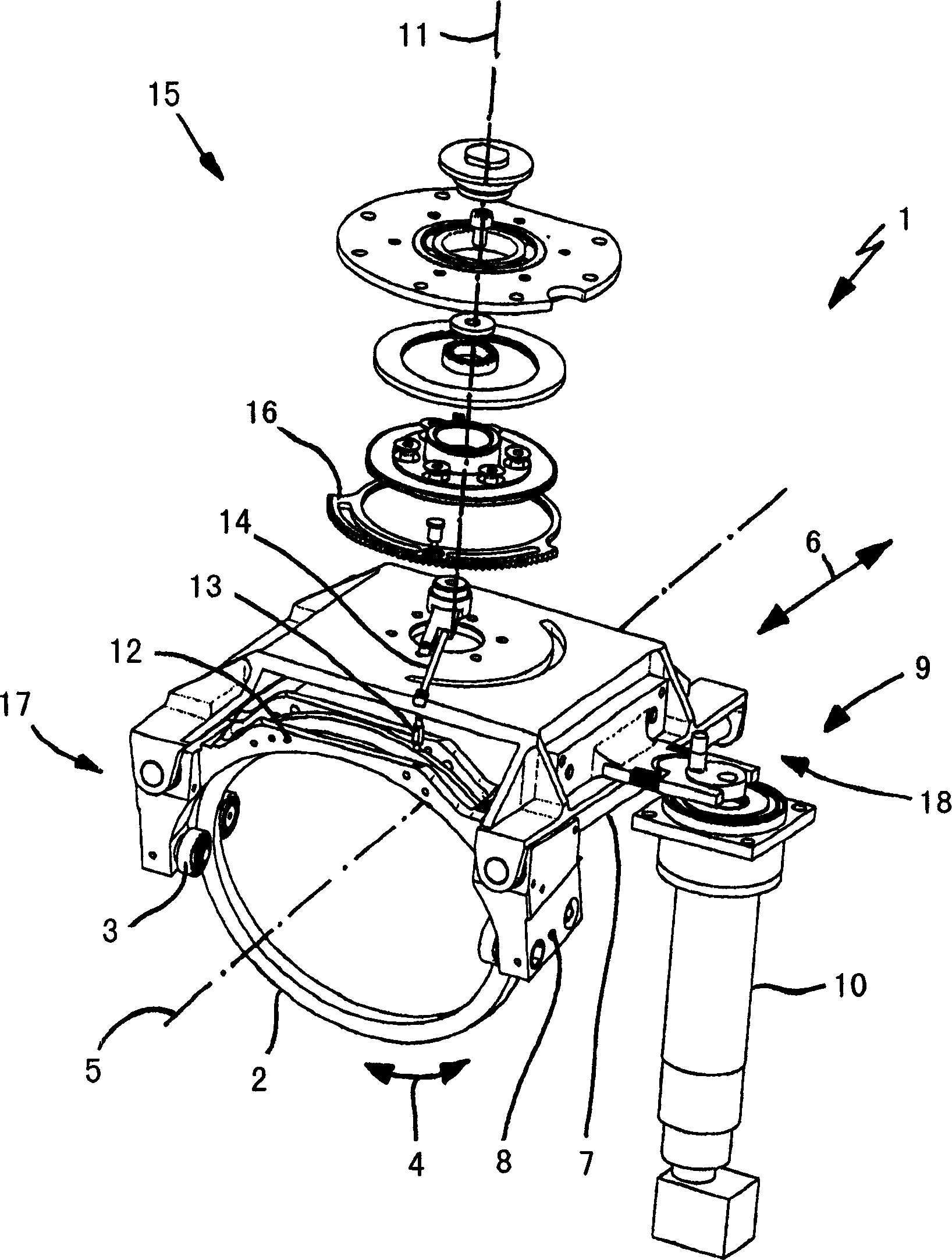
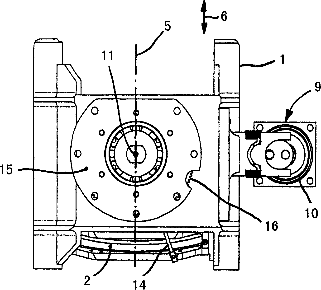
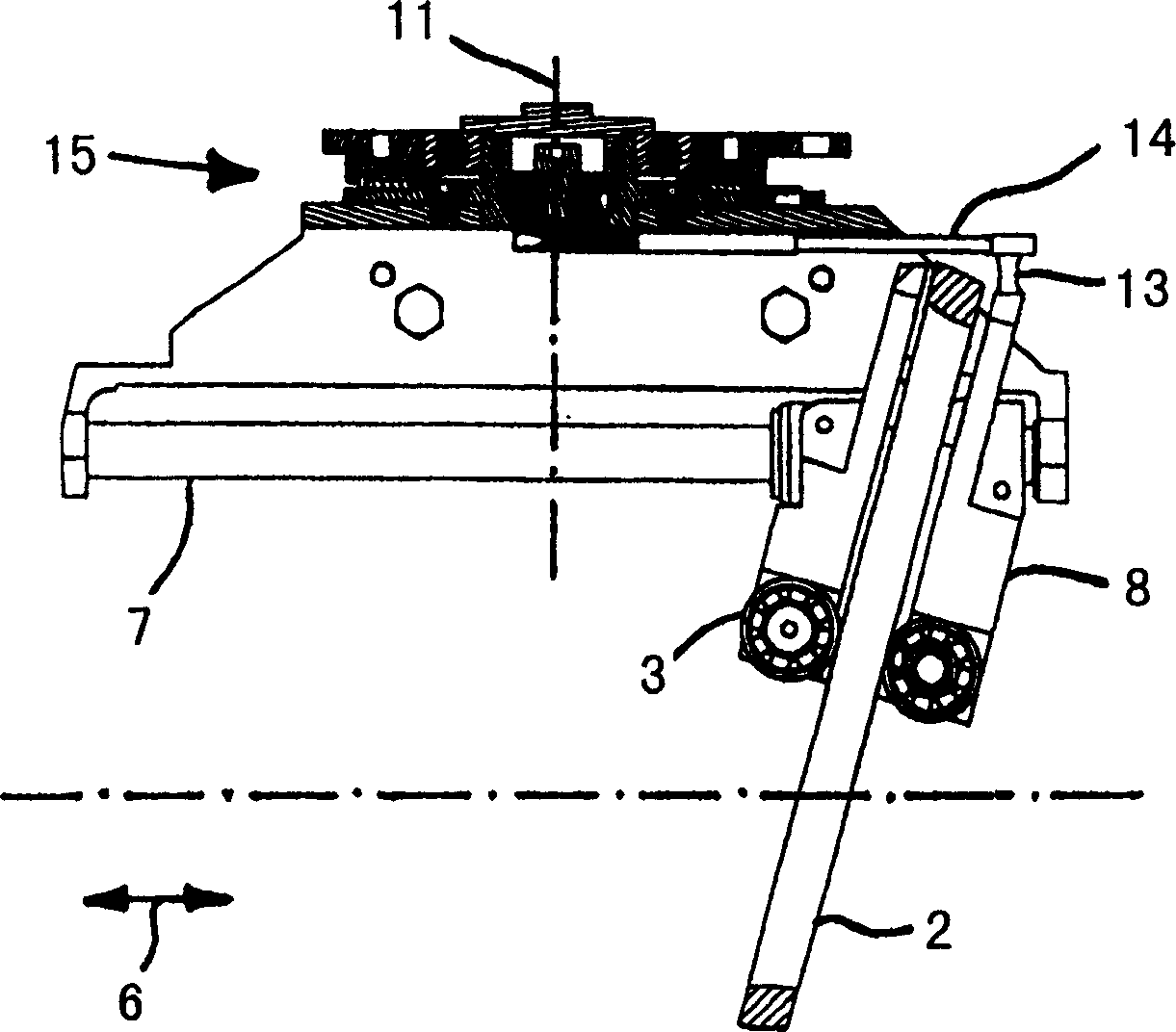
[0030] figure 1 The shown guide 1 guides a friction ring 2 . The friction ring 2 is mounted for rotation about an axis 5 in the direction of the double arrow 4 by means of guide rollers 3 (indicated here only schematically). In order to make the friction ring 2 perform a translational movement in the direction of the double arrow 6 in addition to its rotation in the direction of the double arrow 4, the guide mechanism 1 has two guide shafts 7 (only schematically marked here), on which , a guide slide 8 can translate in the direction of the double arrow 6.

[0031] The guide 1 is operatively connected in its side area 9 to an adjusting axis 10 , so that the entire guide can be rotated about a rotational axis 11 . Depending on how the guide 1 is adjusted about the axis of rotation 11 by the adjusting axis 10 , the guide carriage 8 and the friction ring 2 arranged in the guide carriage move along the axis 5 in one of the two directions of the double arrow 6 .

[0032] In the r...


PUM


Abstract

The present invention relates to a continuously variable transmission, which has at least two transmission elements (cone friction wheels 233, 234) and at least one connecting element (friction ring 237), the friction ring effectively connects these transmission elements and the friction The ring is arranged so that its position can be moved steplessly relative to these transmission elements, wherein the connecting element (friction ring 237) is arranged in a guide mechanism, which is supported rotatably about a rotation axis (211), the rotation The axial direction of the shaft has a component parallel to a plane clamped by the two shafts (231, 232) of the transmission element (conical friction wheels 233, 234).

Description

technical field [0001] The invention relates to a continuously variable transmission having at least two transmission elements and at least one connecting element operatively connecting the two transmission elements to each other and which is arranged so that it can be positioned relative to the transmission elements Stepless movement. Background technique [0002] There are already many continuously variable transmissions in which the position of a connecting element connecting two transmission elements can be infinitely adjusted relative to these transmission elements. For example, a conical friction ring transmission is disclosed from GB-PS298676. In the described embodiment, a guide element is guided on a guide shaft parallel to the axis of the conical friction ring, which guides the friction ring along the conical friction wheel. In this way, a stepless adjustment of the transmission ratio of the conical friction ring transmission is realized. To adjust the friction ...

Claims


Application Information

Patent Timeline
Patent Type & Authority Applications(China)
IPC IPC(8): F16H15/16F16H15/42F16H35/00F16H61/00
Inventor 乌尔里克.罗斯C.德雷格尔T.巴特林W.布兰维特
Owner 乌尔里克·罗斯
Learn More