Array for the illumination of an object

A single-emission, planar technology, applied in projection devices, color photography, semiconductor devices, etc., can solve problems such as complex residual gaps in mechanical fixation, and achieve the effect of large color space

Inactive Publication Date: 2005-07-13
CARL ZEISS JENA GMBH
View PDF1 Cites 21 Cited by
  • Summary
  • Abstract
  • Description
  • Claims
  • Application Information

AI Technical Summary

Problems solved by technology

[0006] Furthermore the presented solution with cross-plates is very complex in terms of mechanical fixation and also has unhelpful residual gaps in the optical path

Method used


Image

  • Array for the illumination of an object
  • Array for the illumination of an object
  • Array for the illumination of an object

Examples


Embodiment Construction

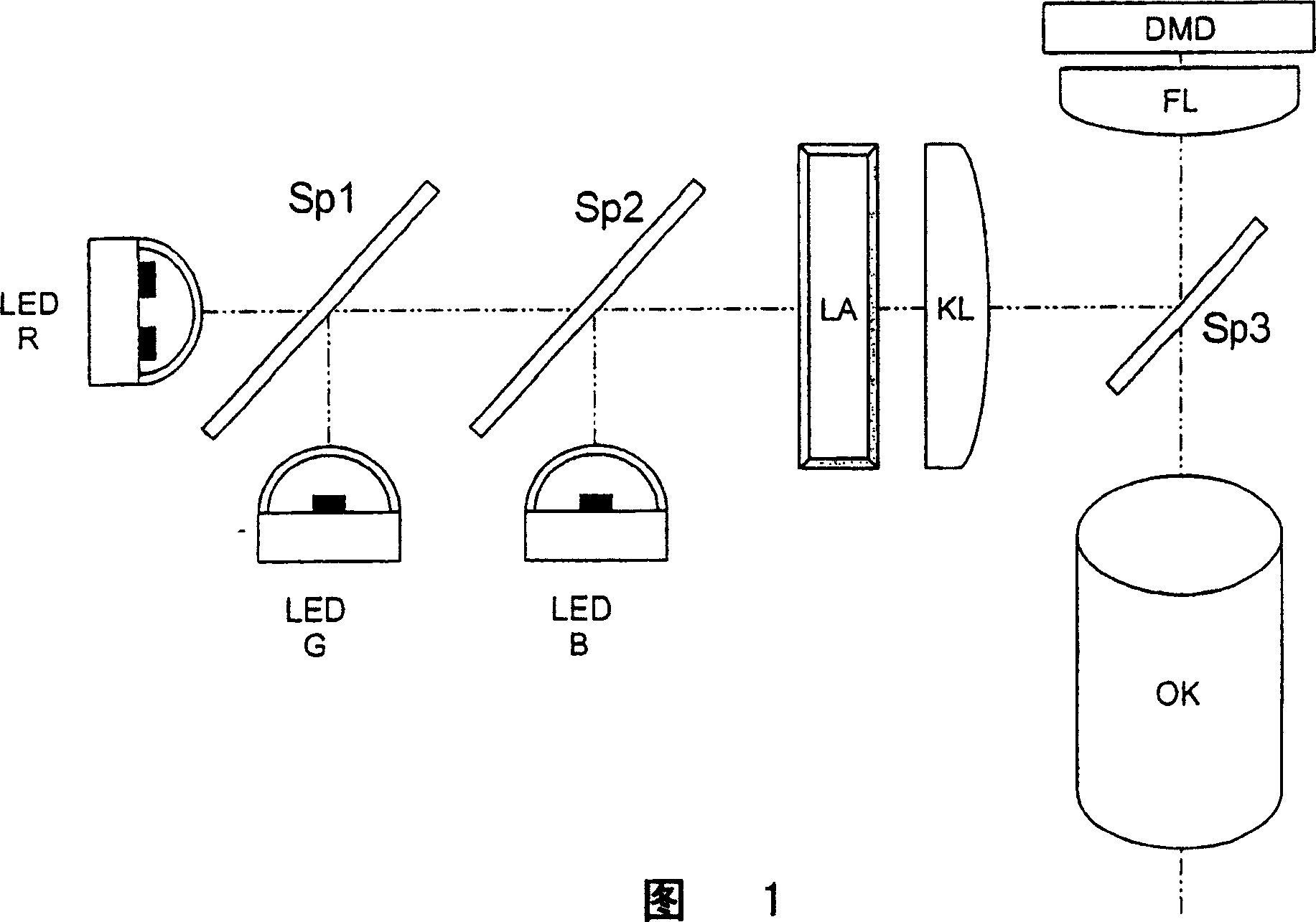
[0030] FIG. 1 shows a device for lighting as described above as prior art, for example on a projector with a DMD matrix.

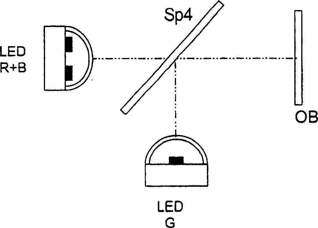
[0031] figure 2 Shown is a single-emitter planar arrangement in the example of a division into two LED modules LED R+B and LED G, whose emitted light components are spatially superimposed via a dichroic beamsplitter Sp4. The superimposed light components are used to illuminate the object OB.

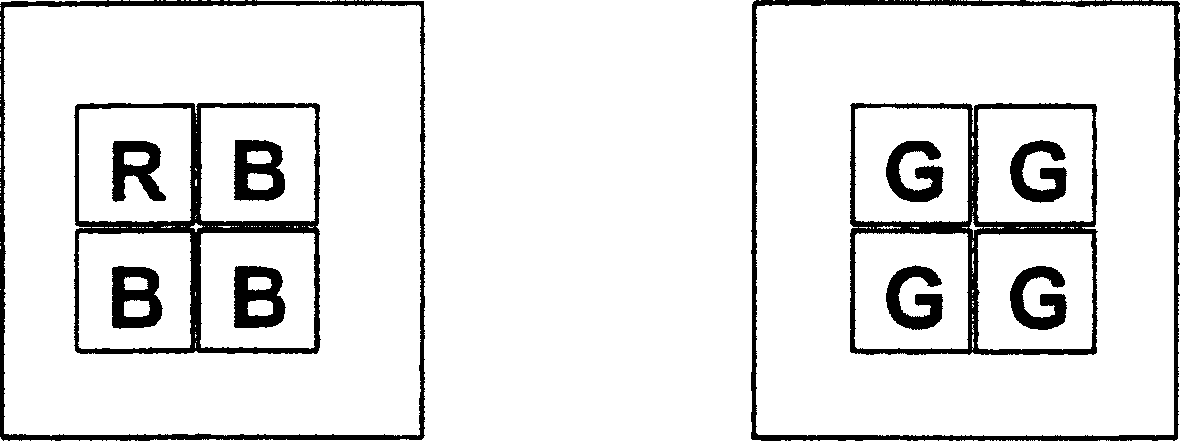
[0032] The first LED module LED R+B comprises three individual emitters for blue and one individual emitter for red. The second LED-module LED G consists of four single emitters of green color (see image 3 ). Currently available LED power ratios are, for example, red:green:blue=6:1:2. Green is the restricted color channel. Three blue emitters and one red emitter are used in one module while maintaining a balanced output power for white light generation. This results in two LED modules with three colors in the appropriate power class, which produce a power rati...


PUM


Abstract

The invention relates to a device for illuminating objects, in particular microdisplays, by means of a planar device of single emitters (LEDs) whose center wavelengths correspond to red, green and blue, respectively, and a device for spatially superimposing light components . The invention is characterized in that a first planar device with a single emitter (LED R+B) and a second planar device with a single emitter (LED G) whose light components are spatially aggregated by means of a beam splitter (Sp4) and single The first planar arrangement of emitters (LED R+B) emits two spectral ranges each with a central wavelength, wherein the power ratios of at least three light components (R, G, B) are determined such that the spatially superimposed light The component produces white illumination light.

Description

technical field [0001] The invention relates to a device for illuminating an object, preferably a microdisplay, by means of a planar device of single emitters whose central wavelengths correspond to the primary colors red, green and blue, respectively, and a device for spatially superimposing light components. Background technique [0002] WO99 / 64912 A1 discloses a lighting unit for a projector with a plurality of planarly extending light sources, such as LEDs. The light components produced by the three LED-arrays, red, green and blue, are combined by dichroic prisms and delivered to the LCD-display. [0003] The disadvantage of using prisms for photopolymerization is that the dichroic layer used is embedded in the glass and encapsulant, there is no refractive index transition from glass to air, and thus only lower refractive index can be achieved than when transitioning to air performance. With the same layer design effort, embedded dichroic layers have a higher s- and p-...

Claims


Application Information

Patent Timeline
Patent Type & Authority Applications(China)
IPC IPC(8): G02B27/10G03B21/14G03B21/20G03B21/28H01L33/00H01S5/00
CPCG03B21/2066G03B33/12
Inventor E·盖斯勒
Owner CARL ZEISS JENA GMBH
Why Eureka
Try Eureka