
Laser welded tube fitting structure and gas generator with the tube fitting structure

A gas generator, laser welding technology, applied in laser welding equipment, manufacturing tools, welding equipment and other directions, can solve problems such as steel type restrictions

Inactive Publication Date: 2005-07-13
NIPPON KAYAKU CO LTD
View PDF0 Cites 2 Cited by
  • Summary
  • Abstract
  • Description
  • Claims
  • Application Information

AI Technical Summary

Problems solved by technology

[0012] However, in this case, there is a problem that the types of steel materials used are limited

Method used


Image

  • Laser welded tube fitting structure and gas generator with the tube fitting structure
  • Laser welded tube fitting structure and gas generator with the tube fitting structure
  • Laser welded tube fitting structure and gas generator with the tube fitting structure

Examples


Embodiment 1

[0062] In FIG. 4 , a JISG3452 SPG steel material of φ60.5 mm and a plate thickness of 3.5 mm is machined into a cylindrical shape to produce a first steel member 1 . Furthermore, JISG3141 SPCD steel material of plate thickness 3mm was press-molded, after that, this was machined, and the cylindrical 2nd steel member 2 which has a flange part was produced.

[0063] This first steel member 1 is inserted into the second steel member 2 to form a flared joint 7 whose bevel shape is a flared レ shape.

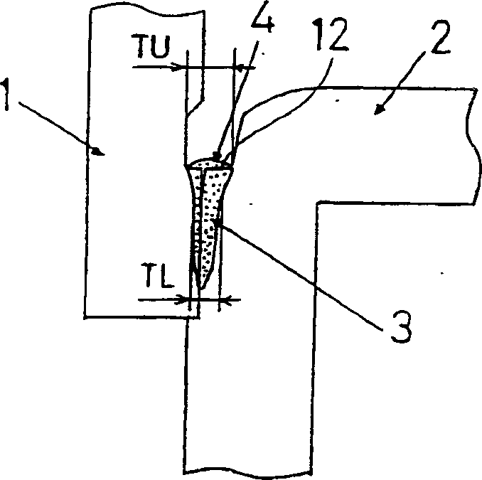
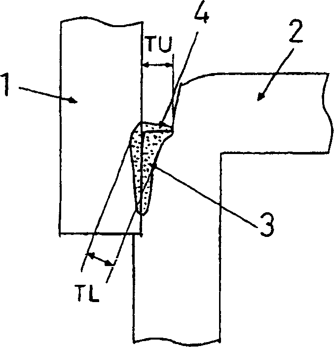
[0064] Then, as shown in FIG. 5( b ), an I-groove-shaped flat portion 4 is formed on the second steel member. The width of the flat portion 4 is TS [mm].

[0065] Moreover, as shown in FIG. 5(c), an I-groove-shaped flat portion 4 is formed on the first steel member and the second steel member. The width of the aforementioned flat portion 4 is TD [mm].

[0066] CO2 laser welding was carried out within the range of welding conditions shown in Table 1 in FIG. 14 . Then, it was checked...

Embodiment 2

[0078] In FIG. 7 , a disc-shaped first steel member 1 is molded by press-forming a JISG3141 SPCD steel material having a plate thickness of 3 mm, and then performing machining. These are combined and embedded in the second steel member 2 having a flange portion to form a flared joint 7 whose bevel shape is a flared V shape.

[0079] Then, as shown in FIG. 8( c ), an I-groove-shaped flat portion 4 is formed on the first steel member and the second steel member. The width of the aforementioned flat portion 4 is TD [mm].

[0080] YAG laser welding is performed on it, and the presence or absence of cracks is investigated through the surface and cross-sectional investigation of the welded part.


PUM

PropertyMeasurementUnit
widthaaaaaaaaaa

Abstract

A laser welded joint structure, which is a laser welded joint structure of a flared joint, is provided with an I-shaped groove-shaped flat portion ( 4). A gas generator having the aforementioned laser welded joint configuration.

Description

technical field [0001] The present invention relates to a welded joint structure in which press-formed steel parts or parts to be welded such as a press-formed product and a steel material are joined by laser welding. [0002] In particular, it relates to a laser welded joint structure of a flare joint (flare groove joint) in which the groove shape viewed in cross-section consists of circular arcs and circular arcs, or circular arcs and straight lines. [0003] Examples of the member to be welded include steel materials constituting automobile parts such as gas generators, building parts, home appliance parts, and the like. [0004] Hereinafter, when the groove shape viewed from the cross-section of the flare joint consists of arcs and arcs, it is called a flare V-groove (flaresingle Vgroove). In addition, when the shape of the groove viewed from the cross section of the flare joint is composed of a circular arc and a straight line, it is called a flare レ-shaped groove (flare...

Claims


Application Information

Patent Timeline
Patent Type & Authority Applications(China)
IPC IPC(8): B23K26/28B23K33/00B60R21/26B60R21/263B60R21/264
CPCB23K26/28B23K33/006B60R21/2644B60R2021/26076B60R2021/2633B60R2021/2648B23K26/282B23K2101/06
Inventor 村井康生青木靖弘
Owner NIPPON KAYAKU CO LTD
Learn More